Configurationmodes, Frontpanelfunctions, Supervisor port – Verilink 1558D (34-00255) Product Manual User Manual
Page 20: Powerindicators, Lockedindicator, Statusindicators, Manual path selector switch, Configuration modes -4, Front panel functions -4, Front panel functions
Operation 3-4
1558D APS CSU/DSU
• Occurrences - Intervals, 1 through 96
• Duration - Intervals, 1 through 96
• Valid Intervals Total
• Occurrences, 24-hour value
• Duration, 24-hour total
• 30-day switch occurrence history
Configuration Modes
Any time that the 1558D unit is initialized (power removed,
then reapplied), all key configuration data is read by the
1558D CPU and implemented based upon the particular
boot mode options selected by the user (see Installation on
page 2-1 for additional information). The four possible
BOOT mode configurations are described below:
1. Boot from Switches - At power up, the 1558D CPU
reads the values set at the rear panel option switches and
configures the unit per those switch settings.
2. Boot from Manager - At power up the CPU sends a
message to the 1559 APS manager for a download of
1558D unit configuration information. Note that this
mode requires that a 1559 site manager be installed.
3. Boot from RAM - At power up, the 1558D CPU reads
the unit configuration from the battery backed RAM
data.
4. Boot from ROM - At power up, the 1558D CPU reads
the factory firmware default values from ROM. The fac-
tory default ROM configuration option settings are:
• Slave operation
• Net A/B B8ZS line coding
• Net A/B ESF framing
• Revert mode, disabled
• Availability timer set to 60 seconds
• Errored seconds set to 20
• Consecutively errored seconds set to 2
• Loss of frame set to enabled
• Loss of signal set to enabled
Front Panel Functions
The front panel of the APS unit contains several LED indi-
cators, a SUPV access port, a path select switch, and several
bantam test access jacks. The following paragraphs briefly
describe the operation of these items (refer to Figure 3-2
and the 1558D Configuration at the end of this manual).
Supervisor Port
The front panel SUPV port allows the user to connect to the
1558D via a PC running the supplied APS LAPS (Local
Access protection software) application. This user interface
software allows the user to gain access to the unit configura-
tion data, unit status, unit performance, and perform local
and remote loopback testing.
Electrically, the SUPV port is RS232 and the data format is
19.2 Kb, asynchronous. The cable used to connect the PC to
the SUPV port is a DB9 (female) to 6-pin modular cable.
This cable is provided with the 1558D unit. The pin func-
tions for the SUPV port are shown in the following table.
Power Indicators
The 1558D has a green power LED indicator located on the
front panel. This indicator will be ON when the unit is con-
nected to a nominal power source of 115 volts, AC. The
1558D draws approximately 75 milliamps. The AC power
cord is approximately 6 feet long and the plug end is an
industry standard 3-prong male connector.
Locked Indicator
The user can manually force and lock either the A or B T1
path as the active path by moving the PATH SELECT switch
from the AUTO position to either the A or B Path Select
positions. This action will force the 1558D to use the
selected path. Also, the 1558D is now manually locked to
this path and will not switch from it, even if the selected
path is in a failed state or subsequently fails. When the
1558D has been manually forced to either the A or B PATH,
the amber LOCKED LED indicator will be on. Moving the
PATH SELECT switch back to the AUTO position will turn
off the LOCKED LED and restore normal APS operation.
Placing the 1558D in a manually
locked mode prevents the unit from
performing automatic protection switch-
ing.
Status Indicators
The 1558D front panel STATUS A and B LEDs (green)
indicate which of the two T1 receive paths (A or B) is pres-
ently being utilized to provide service to the CPE equip-
ment.
Manual Path Selector Switch
The front panel manual PATH SELECT switch is used to
force the 1558D to use either the A or B path as the active
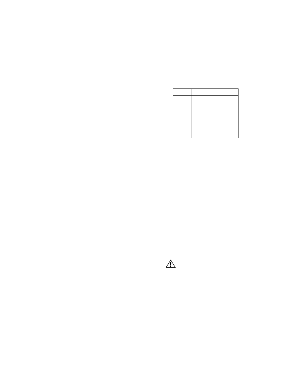
Table 3-A SUPV Pinouts
Pin SUPV Port Wiring
1
Not Used
2
Ground
3
Data Out
4
Data In
5
Ground
6
Not Used