Options switch sw2, Option switch sw3, Option switch sw4 – Verilink 1558D (34-00255) Product Manual User Manual
Page 24: V.35 female interface connector (dce), V.35 female interface connector (dce) -8
Operation 3-8
1558D APS CSU/DSU
Position 7 - This DIP will be used to set the AMI/B8ZS
function for NET A. The factory default setting is B8ZS.
The 1558D will automatically detect and insert a B8ZS code
into any block of data containing eight consecutive zeros.
Position 8 - This DIP will be used to set the AMI/B8ZS
function for NET B. The factory default setting is B8ZS.
The 1558D will automatically detect and insert a B8ZS code
into any block of data containing eight consecutive zeros.
O
PTIONS
S
WITCH
SW2
This eight position DIP switch is used to configure the fol-
lowing APS functions. The function of each of the DIP posi-
tions is described below. Note that the factory defaults are
shown in bold type.
Position 1 - This DIP will be used to set the CSU Enable/
Disable mode. The factory default is CSU mode enable. If
the unit is set to CSU mode disable, the 1558D will not
respond to CSU ESF FDL commands nor will it respond to
I-band CSU loop/unloop codes.
Position 2 - This DIP will be used to set the Path Revert
Enable/Disable mode. The factory default is Path Revert dis-
abled. If the unit is set for Path Revert enabled, the 1558D
will always revert the service back to the A path whenever it
is not in an alarm state.
Positions 3,4 - These two DIP switches configure the LBO
values for Path A (0.0, 7.5, 15, or 22.5 dB). The factory
default is 0 db.
Positions 5,6 - These two DIP switches configure the LBO
values for Path B (0.0, 7.5, 15, or 22.5 db). The factory
default is 0 db.
Positions 7,8 - These two DIPs will be used to set the
1558D timing source (Internal/Master, DTE/External, or T1/
Network) of the 1558D. The 1558D has an Auto Clock
mode. This eliminates the need for the customer to loop
clocking back to the 1558D at the CPE end of the V.35 cable
in those applications where the customer is required to
return external clock leads to the 1558D unit.
O
PTION
S
WITCH
SW3
This eight position DIP switch is used to configure the unit
(shelf/position) address of the 1558D unit.
Positions 1,2,3,4,5,6,7,8 - These eight DIP positions are
used to set the unique unit address (see Installation on page
2-1). The default address is 01 (all switches in the down
position).
O
PTION
S
WITCH
SW4
This 10 position DIP switch will be used to configure the
DSU functions of the 1558D.
Positions 1,2,3,4,5, - These DIPs are used to set the number
of DS0s used by the DTE V.35 port (FT1). The operation
will be the same as the present 300 productivity unit. Note
that DIPS 1 - 5 must be down and in this mode, the speed
will be set to 1.344Mb or 1.536 Mb, depending upon rate
multiple selected. The default is 1.536Mb.
Position 6 - This DIP will set the bit rate multiple to either
56 or 64 Kb. The default is 64Kb, clear channel.
Position 7 - This DIP will set the Contiguous or Alternate
DS0 channel mode. The 1558D can assign bandwidth either
in consecutive DS0 channels beginning with DS0 one or inb
alternate DSO channels beginning with DS0 one. The later
is sometimes required for fractional T1 service supplied by
AT&T. The default is Contiguous.
Position 8 - This DIP will set the Control Flow mode to
either ON or Follows. The 1558D V.35 DTE port can be
optioned for control lines ON or follows. When set to ON,
the 1558D sets CTS, DSR, and CD to the ON state. When
set to FOLLOWS, the DSR follows T1 sync, the CTS fol-
lows RTS, and the CD follows the density status of the
incoming T1 signal (>175 zeros = CD OFF). Note that the
TM line goes high whenever the 1558D is placed in a test
state. The default is ON.
Position 9 - This DIP will set the Data Invert mode to either
No or Yes. In certain data applications, the user data may
contain a high level of zeros and the user cannot operate the
T1 facility using B8ZS. In this application, the 1558D can
invert the data, thereby maintaining T1 density require-
ments. The default is NO.
Position 10 - This DIP is not used (spare)
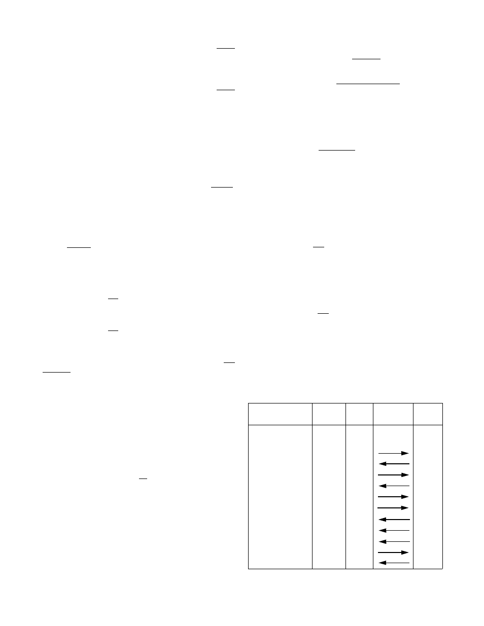
V.35 Female Interface Connector (DCE)
The rear panel 34-pin V.35 female connector is used to
interface the 1558 to the CPE equipment. The pins used in
the interface and their functions are shown in Table 2-C.
Table 3-C. V.35 Female Interface Connector
Function
CCITT
Name
Direction
DTE...1558
1558D
V.35
Frame Ground
101
FG
A
Signal Ground
102
SG
B
Send Data
103
SD
P, S
Receive Data
104
RD
R, T
Request to Send
105
RTS
C
Clear to Send
106
CTS
D
Data Set Ready
107
DSR
E
Data Terminal Ready
108
DTR
H
Data Carrier Detect
109
DCD
F
Transmit Clock
113, 114
TC
Y, AA
Receive Clock
115
RC
V, X
External Clock
113
ext.TC
U, W
Test Mode
142
TM
K