Dte control lines, Combusconnections, Networkt1connections – Verilink 1558D (34-00255) Product Manual User Manual
Page 25: Com bus connections, Network t1 connections
Operation 3-9
1558D APS CSU/DSU
DTE Control Lines
The DTE port can be optioned for control lines ON or fol-
lows. When set to ON, the 1558D sets CTS, DSR, and CD
to the ON state. When set to FOLLOWS, the DSR follows
T1 sync, the CTS follows RTS, and the CD follows the den-
sity status of the incoming T1 signal (>175 zeros = CD
OFF). Note that the TM line goes high whenever the 1558D
is placed in a test state.
COM Bus Connections
The two 6-pin modular connectors labeled COM BUS IN
and COM BUS OUT on the rear panel may be used to con-
nect to the optional 1559 APSM site manager. These ports
are wired to allow daisy chaining one or more units off of
the APSM (the OUT port is connected to the IN port from
unit to unit). The COM BUS IN and OUT connectors are
physically RJ-11, 6 -pin modular jacks. The function of the
6 pins are described in the table below. For additional infor-
mation concerning the site manager, consult the TxPORT
1559 manual.
Network T1 Connections
The NET A and the NET B T1 modular jacks are used to
connect the 1558D to the T1 facilities using RJ-48 modular
cables. Physically, the 1558D NET A and NET B connec-
tors are RJ48, 8-pin modular connector. The usage of each
of the eight pins found in the connector are described in the
table below. The 1558D unit comes with two ten-foot RJ-48
cables (NET A, NET B, and DTE).
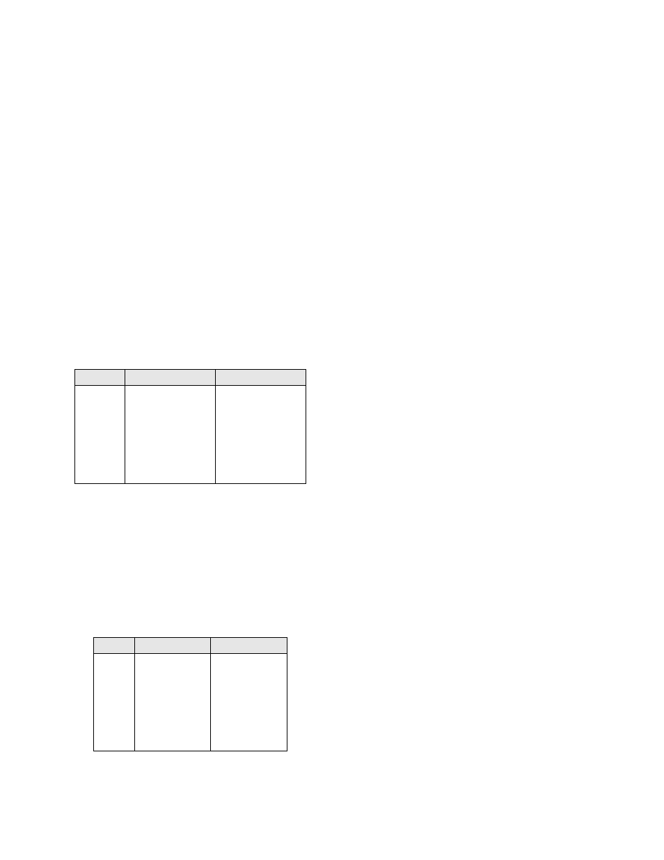
Table 3-D. COM Bus Pinouts
PIN
COM BUS IN
COM BUS OUT
1
Not Used
Not Used
2
Signal Ground
Signal Ground
3
Data, output
Data, Output
4
Data, input
Not Used
5
Signal Ground
Signal Ground
6
Not Used
Not Used
Table 3-E. T1 Connections
PIN
NET A
NET B
1
Data In (Tip)
Data In (Tip)
2
Data In (Ring)
Data In (Ring)
3,6
Not Used
Not Used
4
Data Out (Tip)
Data Out (Tip)
5
Data Out (Ring)
Data Out (Ring)
7,8
Not Used
Not Used