Ac power, Configurationmodes, Switchconfiguration – Verilink 1558D (34-00255) Product Manual User Manual
Page 11: Optionswitchs1, Option switch s2, Ac power -3, Configuration modes -3, Switch configuration -3, Option switch s1 -3 option switch s2 -3, Configuration modes
Installation 2-3
1558D APS CSU/DSU
AC Power
The 1558D unit operate from 115 VAC, 75 mA maximum.
The unit is shipped with a 5.5 foot 3-prong industry standard
AC power cord. After all wiring connections have been
completed, attach the unit to the AC wall receptacle. The
unit responds by turning on the front panel (green) LED
power indicator. The user is now ready to configure the
1558D. The following sections describe how to quickly con-
figure the 1558D unit.
Configuration Modes
Any time that the 1558D unit is initialized (power removed,
then reapplied), all key configuration data is read by the
1558D CPU and implemented based upon the particular
configuration boot mode options selected by the user. There
are four possible configuration boot modes:
• Configure/Boot from Switches.
• Configure/Boot from ROM.
• Configure/Boot from RAM.
• Configure/Boot from Manager. This requires the optional
1559 manager.
All factory default settings in this manual are
shown underlined.
Switch Configuration
After the equipment has been unpacked and inspected and
mounted, the next step is to configure the unit. All unit
options are set by the manual DIP switch positions located
on the four rear panel option switches (S1, S2, S3, and S4).
The 1558D is shipped from the factory with all option
switches in the OFF (factory default) positions. The follow-
ing paragraphs briefly describe the 1558D option switches
and there functions.
After the option switches have been set to the
desired operating mode, recycle the power to the
unit. At power up, the CPU will read and imple-
ment the switch settings.
O
PTION
S
WITCH
S1
Switch S1 is an eight position DIP switch used to set the
following unit options.
• Master or Slave Card Operation
• Boot general parameters from Switches, ROM, RAM, or
Manager
• Boot alarm parameters from ROM or RAM
• Enable/Disable Framing Error Alarm
• Enable/Disable Loss of Signal Alarm
• AMI/B8ZS Line Encoding, NET A, NET B
The following table describes the DIP switch settings con-
trolled by Switch S1.
O
PTION
S
WITCH
S2
Switch S2 is an eight position DIP switch used to set the
following unit options.
• CSU Mode, Enable/Disable
• Path Revert, Enable/Disable
• NET A, LBO Value
• NET B, LBO Value
• Clocking Mode, Internal, External, Network
Table 2-G describes the DIP switch settings controlled by
Switch S2.
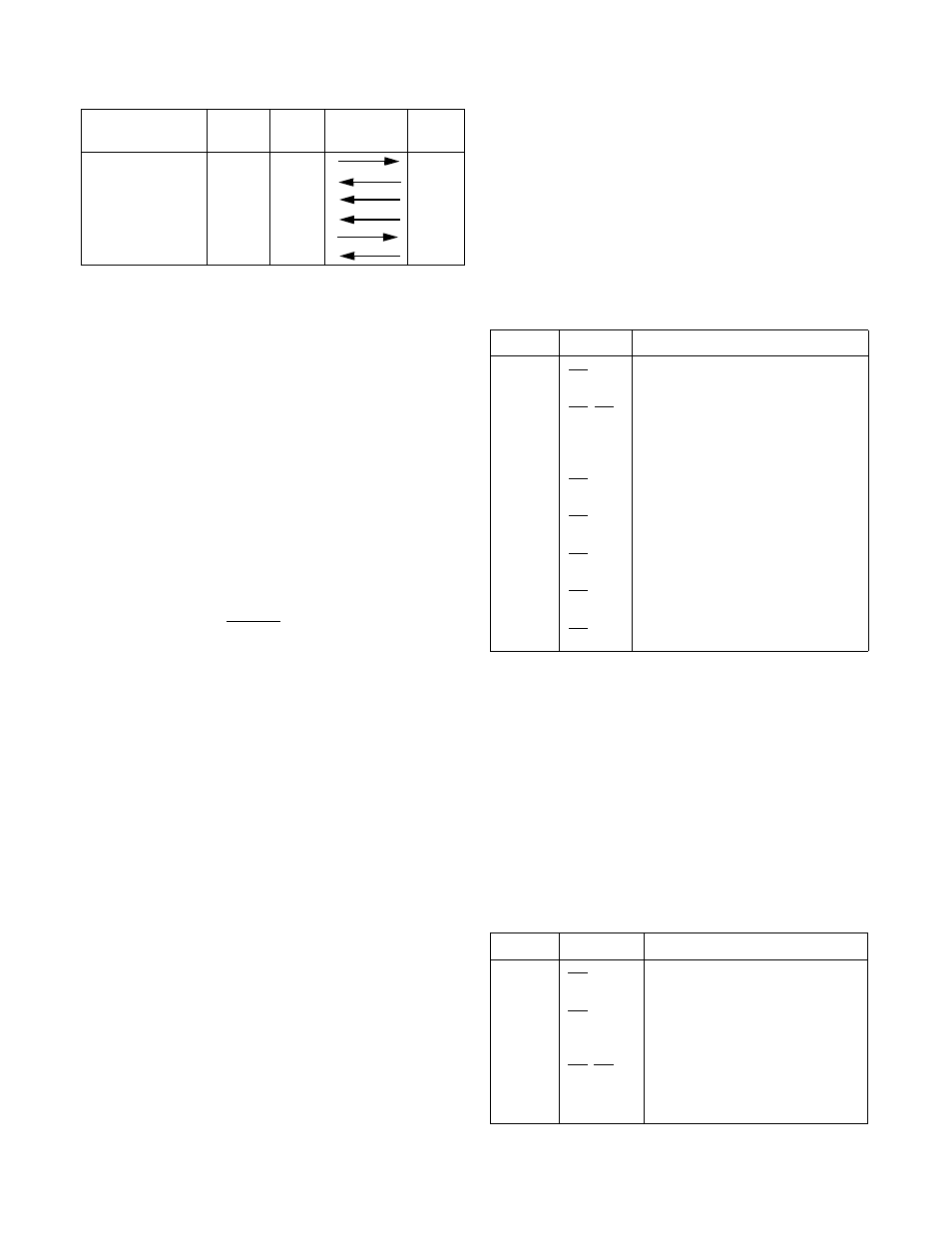
Data Terminal Ready
108
DTR
H
Data Carrier Detect
109
DCD
F
Transmit Clock
113,114
TC
Y, AA
Receive Clock
115
RC
V, X
External Clock
113
ext.TC
U, W
Test Mode
142
TM
K
Table 2-E V.35 Pinouts
Function
CCITT
Name
Direction
DTE/DCE
1558D
V.35
Table 2-F Switch S1
Position Selection
Switch S1 Description
1
Off
On
Card Function, Slave
Card Function, Master
2,3
Off, Off
Off, On
On, Off
On, On
Boot from Switches
Boot from Manager
Boot from RAM
Boot from ROM
4
Off
On
ARM from ROM
ARM from RAM
5
Off
On
Enable Frame Error Alarm
Disable Frame Error Alarm
6
Off
On
LOS, Enabled
LOS, Disabled
7
Off
On
NET/A, B8ZS
NET/A, AMI
8
Off
On
NET/B, B8ZS
NET/B, AMI
Table 2-G Switch S2
Position Selection
Switch S2 Description
1
Off
On
CSU Mode, Enabled
CSU Mode, Disabled
2
Off
On
Path Revert, Disabled
ON = Path Revert, Enabled
3,4
Off, Off
Off, On
On, Off
On, On
NET A LBO Value
0.0 dB
7.5 dB
15.0 dB
22.5 dB