Tri Tool 620SB Clamshell Hydraulic User Manual
Page 24
24
TRI TOOL INC.
92-0282 : Rev. 131230
NOTE:
NOTE:
Tool Bit Set Up
When the Tool Bits sever the pipe, disengage the Feed Pin and let the Headstock
rotate 2 to 3 times to clear the chip.
Go back to “When the machining operation is finished..”
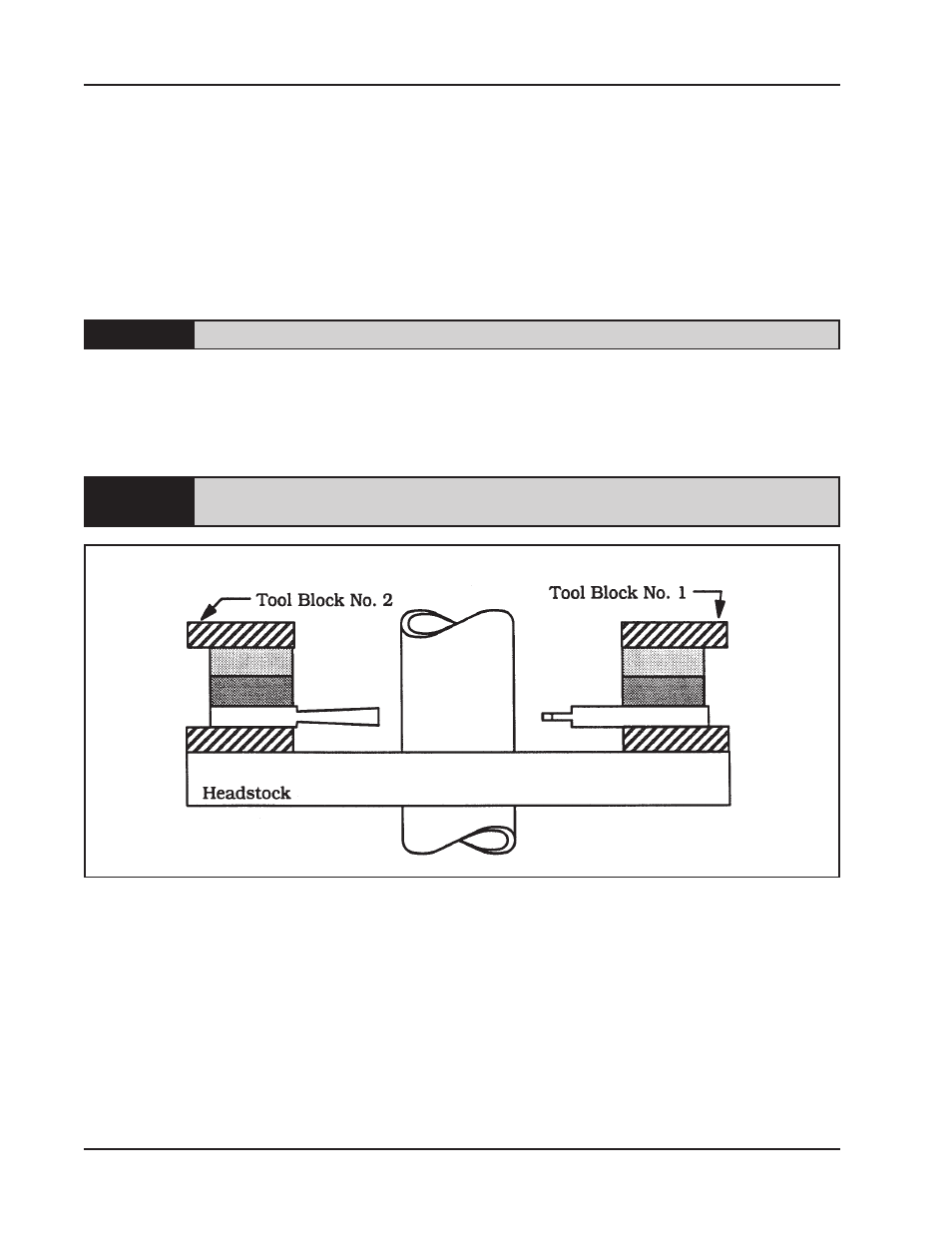
TOOL BIT ADJUSTMENT FOR PART OFF AND DOUBLE BEVEL
Install Tool Bits A, D, and E into Tool Block No. 1 along with two Spacers S3 and S4.
Either Tool Block may be designated as No. 1.
Position the Spacers flush with the inside face of the Tool Holder.
Position Tool Bits D and E approximately 1/2” (12.7 mm) outward from the cutting
edge of Tool Bit A.
Tool Bits D and E will be repositioned to contact the beveled surface as the
cutting
progresses.
Tighten the Set Screws holding Tool Bits A, D, and E.
Install the Tool Bits B and C into Tool Block No. 2 along with the two Spacers S1
and S2.
Position the Spacers flush with the inside face of the Tool Holder.
Tool Bits B and C should be the same distance inward from the Tool Holder.
Tighten the Set Screws holding Tool Bits B and C.