Tri Tool 602TSB Clamshell Air User Manual
Page 24
24
TRI TOOL INC.
92-0139 : Rev.131230
WARNING:
CONFIGURE THE CLAMSHELL FOR THE SPECIFIC TASK REQUIRED
Select the proper Tool Blocks. Refer to the charts ‘Tool Blocks’.
Mount the Tool Blocks and Tripper Block to the Clamshell.
Check the adjustment of the slides and mesh of the Tripper Pin with the Feed
Sprocket.
Select the proper Clamping Pad Set. Refer to the charts ‘Clamping Pad Sets’.
Install the Clamping Pad Set into the Clamshell.
If using the Fixed Clamping Pad Set then install the Clamping Pad Set so that the
tube lays on the Fixed Pads or vice versa.
Fixed Pads should be located 90
o
from each other.
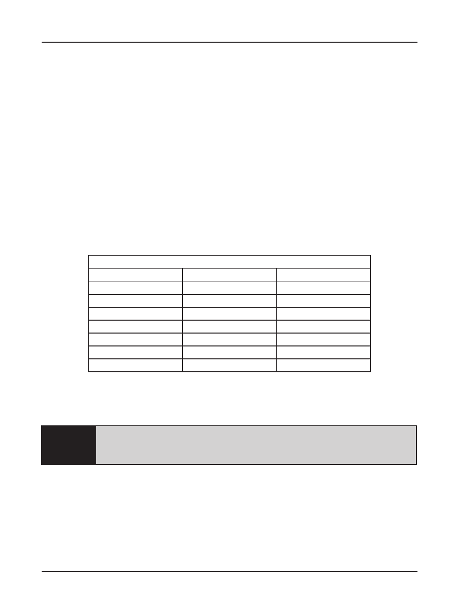
Pad Set Selection
Pipe Size
OD
Pad Set P/N
2.000" 50.8 mm
67-3152
1 1/2"
1.900" 48.3 mm
67-3216
1.875" 47.6 mm
67-3217
1.750" 44.5 mm
67-3155
1 1/4"
1.660" 42.2 mm
67-3218
1.625" 41.3 mm
67-3219
1.500" 38.1 mm
67-3220
TOOL BIT SET-UP
Select the proper Tool Bit set. Refer to the section ‘Tool Bits’.
Use of dull or improperly designed Tool Bits or Tool Bits not manufactured by
TRI TOOL Inc. may result in poor performance and may constitute abuse of
this machine and therefore voids the TRI TOOL Inc. factory warranty.
Install the Tool Bits into the Tool Blocks. Refer to the section ‘Tool Bits’ for installation
drawings.
Approximately .50” (12.7 mm) should be protruding from the end of the Tool Holders.
Tighten the Tool Bit Set Screws, then verify that there is adequate clearance
between the Tool Bits and the tube by rotating the Headstock by hand.