Tecfluid MX4 For FLOMAT Series User Manual
Page 13
13
MOUNTING
In order to make the positioning of the insert in the pipe easier, there is a label on one of
its sides with markings indicating the position of the internal pipe diameter for each DN.
Cut this label above the line corresponding to the DN of the pipe, at a distance equal to
the pipe thickness. Peel off the bottom part of the label. Once the insert is placed into its
final position, where the label was cut must coincide with the outer diameter of the pipe.
This ensures that the measuring electrodes penetrate far enough in the area of flow
profile that will allow an accurate measurement.
DN
Sensor
length
Insert
length
C
(H)
80
101
93
10
88-s
100
12,5
85,5-s
125
15,5
82,5-s
150
19
79-s
200
25
73-s
250
31
67-s
300
37,5
60,5-s
350
44
54-s
400
50
48-s
500
206
145
62,5
140,5-s
600
75
128-s
700
87,5
115,5-s
800
100
103-s
900
112,5
90,5-s
1000
125
78-s
1200
356
190
150
203-s
1400
175
178-s
1600
200
153-s
1800
225
128-s
2000
250
103-s
Qnom
m
3
/h
90,5
141,3
220,9
318,1
565,5
883,6
1.272.,3
1.731,8
2.261,9
3.534,3
5.089,4
6.927,2
9.047,8
11.451,1
14.137,1
20.357,5
27.708,8
36.191,1
45.804,4
56.548,7
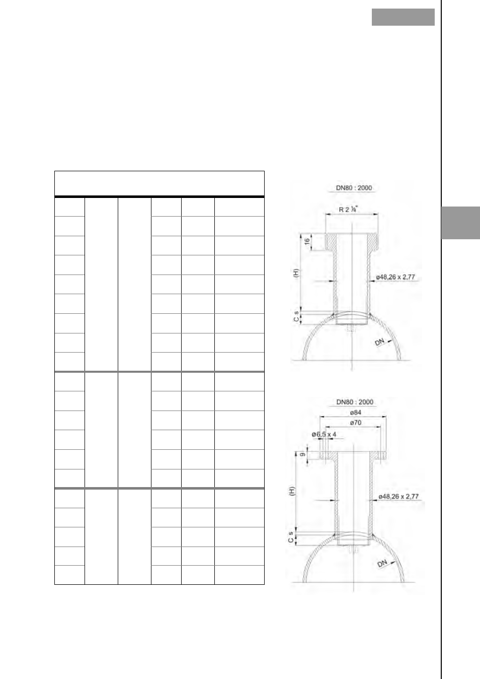
Threaded insert
Flanged insert
5