Tecfluid XT5 User Manual
Page 8
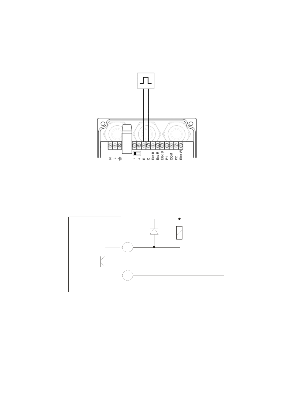
2.3 Pulse
output
connection
Terminal
E
Emitter.
C
Collector.
8
2.4 Connection
examples
The two usual ways to connect the alarm outputs are NPN or PNP modes, depending on if
the load is connected to the positive or negative terminal.
In the following figures, an example of connection for the alarm 2 in NPN and PNP mode can
be seen.
The pulse output is opto-isolated. The terminals are the collector and emitter of an NPN
bipolar transistor. Optionally this output can be supplied for AC loads (see 9.3).
In the case of using inductive loads, in order to protect the output transistor, the use of
free wheeling diodes is required.
E
Coil
XT5
C
This manual is related to the following products: