Setting up the tascam ds-m7.1, Trimming the levels – Teac DS-M7.1 Setup Guide User Manual
Page 2
Setting up the TASCAM DS-M7.1
2
TASCAM DS-M7.1 Setup Guide
Setting up the TASCAM DS-M7.1
TASCAM DS-M7.1 Setup Guide
3
Trimming the levels
When monitoring in surround mode, it is important that the perceived level of each channel (as perceived from the
monitoring position) is equal, in order to achieve a satisfactory mix.
NOTE
Before proceeding further with these operations, it is important that you ensure that the input mode
of the DS-M7.1 reflects the setup you are using and the output channels are “patched” so that the
names of the channels correspond to the actual channels that you have set up in your system (if the
channel meant to be driving the LFE is actually driving one of the surround channels, you will have
severe problems!). Use the
INPUT and OUTPUT keys (shifted STATUS and SYSTEM) keys for this. See
the main manual if this setup has not been done already and you are unsure of the procedures.
The DS-M7.1 provides you with a pink noise generator to allow you to set up and calibrate your monitoring sys-
tem for optimal results. You will also need an SPL (sound pressure level) meter. Absolute accuracy in this case is
not of prime importance—relative levels are what are being set up here.
There are two standard weightings that are commonly used, and may be selected from most SPL meters: the ‘C’
weighting, providing an almost uniform response from 32 Hz to 10 kHz, and the “A” weighting, which is concen-
trated on the 500 Hz to 10 kHz range. For full-range music productions, use the “C” weighting.
TIP
When you make the measurements described here, either stand the SPL meter on a tripod (ideal), or
hold it to one side of your body, to avoid reflections, etc. caused by your body which can affect the
final results.
Generating the pink noise
Make sure that your monitoring system is turned on, and adjusted to a nominal level.
With the
SHIFT
indicator lit, press the
BASS MGT/TEST
key
to bring up the screen at left. This allows you to select the type
of pink noise generated by the unit, as well as the level of the
noise.
The
Safety
parameter at the bottom of the screen, when
set to
ENABLE
, turns off the ability to switch on the TEST
mode and the pink noise generator. To enable the TEST mode,
set the
Safety
parameter to
DISABLE
.
You will use the
FULL BAND
noise setting in most situations (the alternative is
BAND LIMIT
, which uses
a filter to weight the noise).
There are a number of different selectable levels at which the noise can be output:
-20
,
-18
,
-16
,
-10
,
- 5
and
0
(all relative to full-scale). If you are working to the SMPTE standard, therefore,
-20
corresponds to the
analog nominal level (the EBU equivalent is
-18
—the TASCAM
-16
level is also provided for con-
venience).
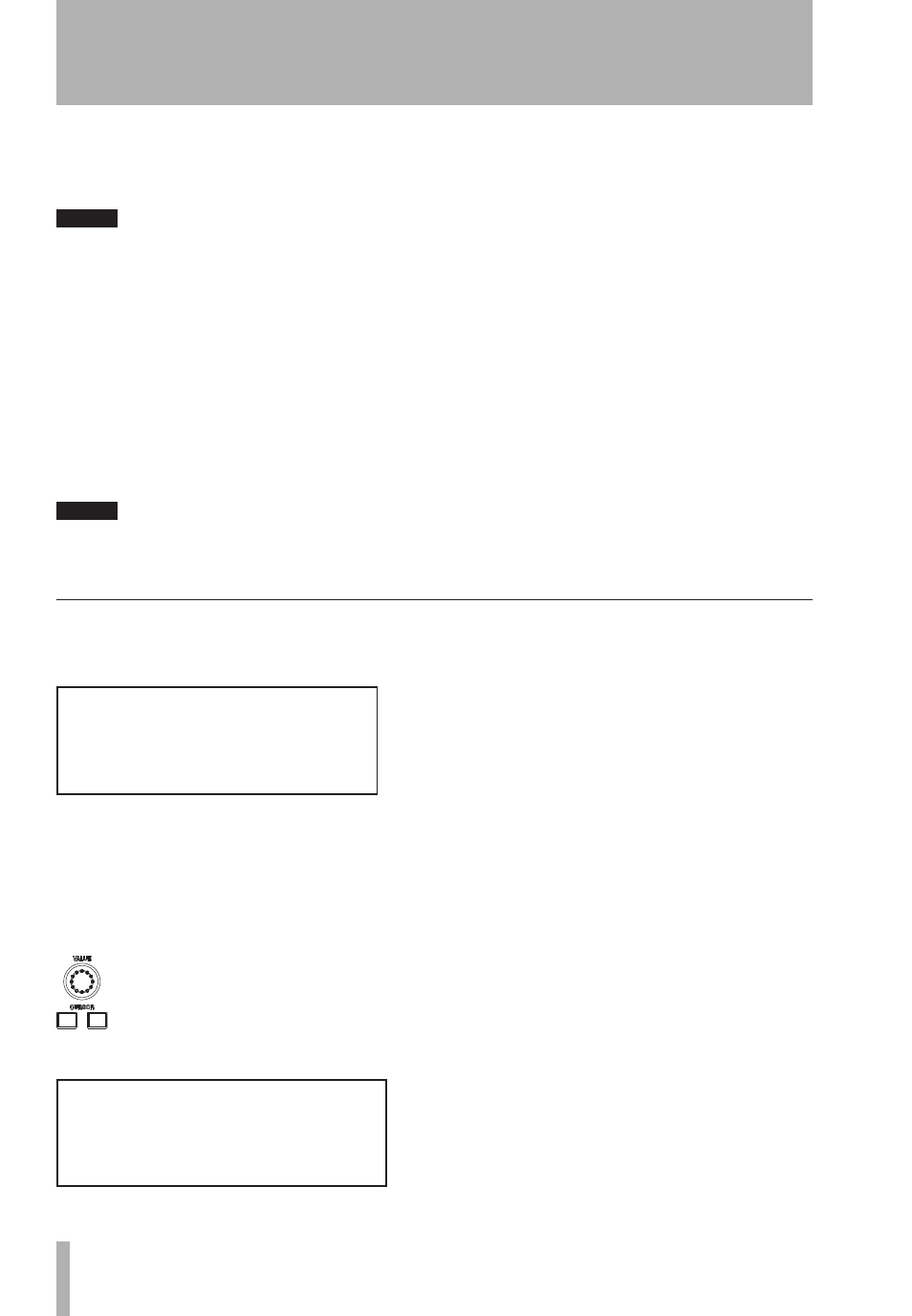
Use the
CURSOR
keys to select the
Level
field, and the
VALUE
dial to adjust the level to the set-
ting you want to use for your calibration.
Now press the
TEST
key on the bottom right of the control panel.
The channel
MUTE CONTROL
keys are used to select the
channels to which the pink noise will be output. When an
input mode is selected, the green indicators under the “ac-
tive” channels are lit, to show that the channel can be used.
For example, if the stereo mode is selected, only the L and
R indicators are lit. In the case of 5.1,
L
,
C
,
R
,
LFE
,
LS
and
RS
are lit.
[TEST]
PNoise FULL BAND
Level -10dB
Safety ENABLE
[TRIM]
L 0.0 C
0.0 R 0.0
LFE 0.0
LS 0.0 RS 0.0