Super Systems XGA Viewer User Manual
Page 43
XGA Viewer Operations Manual
Super Systems Inc.
Page 43 of 46
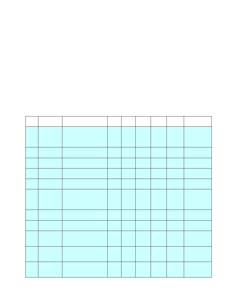
Appendix 1: PGA3500/MGA6000 – Template Channel 1 Data Definitions
This section will display the channel 1 data definition variables for the PGA3500 and MGA6000
templates that are used in the XGA Viewer software. This section is meant to be a reference for
users.
Note: These values are only suggested values, but it is recommended that these values
be used
. The trend values in light blue apply to both the PGA and MGA template, while the trend
values in light gray apply only to the PGA template. Each trend value has nine main points:
•
Slot – The slot that the trend value will be located in
•
Name – The name of the trend value
•
Description – A description of the trend value
•
Src Dec – The number of decimals that the source value has
•
Disp Dec – The number of decimal places to display
•
Units – This will be the units the value will be representing, such as % or °F/°C
•
Min – This is the suggested chart y-axis minimum value
•
Max – This is the suggested chart y-axis maximum value
•
Exp – This can be an expression to view the data
Slot
Name
Description
Src
Dec
Disp
Dec Units
Min
Max
Exp
0
IR %C
% Carbon as
computed by CO,
CO2, and CH4 values
with IR Temperature
2
2
%
0.00
2.00
None
1
IR TEMP
Temperature of the
gas in the furnace
0
0
°F or
°C
0
2000
None
2
% CO
Measured % Carbon
Monoxide
2
2
%
0
25
None
3
% CO2
Measured % Carbon
Dioxide
4
3
%
0
2
None
4
% CH4
Measured % Methane
/ Natural Gas
2
2
%
0
25
None
5
PB %C
% Carbon as
computed by the
atmosphere
controller
2
2
%
0.00
2.00
None
6
PB TEMP Temperature of the
probe
0
0
°F or
°C
0
2000
None
7
PB MV
Millivolts from the
probe
0
0
MV
0
1300
None
8
PB COF
CO Factor in the
atmosphere
controller
0
0
None 0
300
None
9
PB PF
Process Factor in the
atmosphere
controller
0
0
None 0
300
None
10
% O2
Measured % Oxygen
from electrochemical
sensor
1
0
%
0
25
None