Super Systems MGA6000 User Manual
Page 9
SSi Manual #4563 Rev. D Page 9 Multi-Gas Model 6000
Level 2 pass code (default = 2). Page 29 requires the Super Systems Inc special passcode to access. The default pass
codes can be changed by accessing the
Set Pass Codes
(menu option 25) menu.
At the bottom of the Menu Screen is a status bar. This tells the current date and time, and also displays the internal
temperature (IT) of the instrument. This internal temperature should never exceed 122°F (50°C).
Note about Menu Numbers
Each menu screen has a unique number that will be displayed in the upper left-hand corner of the screen. This number
is shown for reference. If you know the menu number of the screen that you would like to go to, this number can be
typed in to access it directly from the
Main Page
(Menu option 1) or the Menu List.
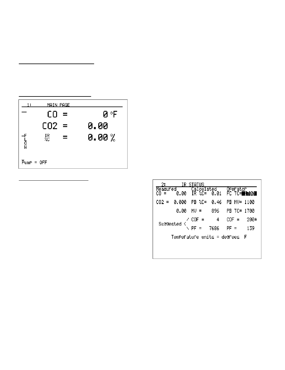
Main Page – Menu Page 1
The IR status display shows the current readings of the
gases being sampled. Depending on the configuration of
your instrument, this screen will show the values from one
to four gases or calculations. To change how the gases
are displayed, use the menu option
Main Display Setup
(menu option 21). Also shown is the relative flow rate of
the sample by a fuel gauge in the left-hand side of the
screen. The “Pump = OFF” message in the lower left-hand
side shows the status of the pump. When the pump is in
auto mode, this message will read “Pump = AUTO”.
IR Status – Menu Page 2
Depending on the configuration of the instrument, this
screen may not contain all of the information shown in
the example. For one- and two-gas configurations, the
“Calculated” values will not be shown, since there is not
enough information available for the instrument to
compute the percent carbon. When the instrument is
configured with three gases (CO, CO2, and CH4), carbon
percentage can be calculated by the instrument, The IR
Status Display provides the user with the calculated
carbon percentage (%C) from two different sources
(probe and infrared). It provides information to allow
the atmosphere controller to be “tuned” to match the
information from the 3-gas analyzer.
To obtain the most information from this screen, data from the carbon probe must be entered. This can
either be done manually or automatically via RS485 communications. This information is displayed at the
right hand side of the screen under the heading
Operator
. Using the keypad to enter numbers, and the
arrow keys to move the highlighted area up and down, the following data should be entered:
• FC TC= The furnace thermocouple value, or the furnace temperature.
• PB MV= The millivoltage from the carbon probe.
• PB TC= The probe thermocouple value, or the probe temperature.
• COF= The CO Factor value read from the SSi, Honeywell, Barber Colman, Yokogawa, or other
atmosphere controller.
• PF= The Process Factor value read from the Marathon Sensors atmosphere controller.