7 smt391 pcb view, Smt391 pcb view – Sundance SMT791 User Manual
Page 18
7 SMT391 PCB View
If the SMT391 is mated with a main board that plugs in a PXIe rack, the combination
will require two PXI slots.
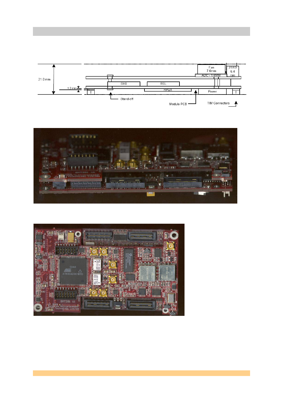
Figure 10: Side view of SMT391 (Height).
Figure 11: Side view of SMT391 (No Heat Sinks) mounted on a board.
Figure 12: Top view of SMT391 (No Heat Sinks).
The following diagram indicates the location of all the important connectors and
components on the SMT391 PCB. This specific diagram is for an AC coupled analog
input stage using a Macom transformer. It is also possible to order the module with
a different input stage for DC coupled applications.
User Manual SMT791
Page 18 of 18
Last Edited: 12/10/2010 09:52:00
See also other documents in the category Sundance Equipment:
- SMT107 (16 pages)
- SMT6035 v.2.2 (39 pages)
- SMT6012 v.4.6 (22 pages)
- FC100 (12 pages)
- FC108 v.1.1 (10 pages)
- SMT6065 v.4.0 (45 pages)
- FFT v.2.1 (19 pages)
- SMT111 (18 pages)
- SMT118LT (10 pages)
- SMT118 (20 pages)
- SMT123-SHB (13 pages)
- SMT128 (15 pages)
- SMT145 (18 pages)
- SMT148 (35 pages)
- SMT130 v.1.0 (46 pages)
- SMT148FX (48 pages)
- SMT310Q (55 pages)
- PARS (70 pages)
- SMT166-FMC (52 pages)
- SMT166 (44 pages)
- SMT300Q v.1.6 (61 pages)
- SMT310 v.1.6 (50 pages)
- SMT317 (24 pages)
- SMT326v2 (24 pages)
- SMT338 (19 pages)
- SMT349 (32 pages)
- SMT339 v.1.3 (27 pages)
- SMT338-VP (22 pages)
- SMT358 (25 pages)
- SMT351T (37 pages)
- SMT351 (25 pages)
- SMT350 (45 pages)
- SMT362 (30 pages)
- SMT365G (23 pages)
- SMT364 (37 pages)
- SMT373 (15 pages)
- SMT368 (24 pages)
- SMT370v3 (46 pages)
- SMT377 (22 pages)
- SMT381 2007 (31 pages)
- SMT381-VP (81 pages)
- SMT387 (42 pages)
- SMT391 (18 pages)
- SMT384 (47 pages)
- SMT390-VP (55 pages)