Cables and connectors, Comports, Buffered comport cabling – Sundance SMT410 v.1.0 User Manual
Page 46: 17 cables and connectors
User Manual (QCF42); Version 3.0, 8/11/00; © Sundance Multiprocessor Technology Ltd. 1999
17 Cables and Connectors
17.1 ComPorts
The cables used with FMS connectors are not supplied with the SMT410. You can
order them separately from Sundance with part number SMT500-FMSxx, where xx is
the cable length in centimetres.
17.2 Buffered ComPort Cabling
Connecting between buffered ComPorts requires a 1 to 1 cable; the SMT502-Buffer
is the recommended cable assembly and can be purchased separately.
Cable plugs
3M Scotchflex 10126-6000EL FES part 038740A
Plug shells
3M Scotchflex 10326-A200-00 FES part 038760D
Cable type
3M Scotchflex KUCKMPVVSB28-13PAIR FES part 038781E
This cable has 13 individual pairs, with an overall shield, and an outer diameter of
7mm. Cable length should be as short as possible. The maximum tested cable length
is 1 meter.
On reset, each ComPort initialises to being either an input or an output.
Do not connect ‘Reset to Input’ ComPorts together.
Do not connect ‘Reset to Output’ ComPorts together.
However if this should occur, no damage will result, because ComPort direction
signals disable relevant ComPorts.
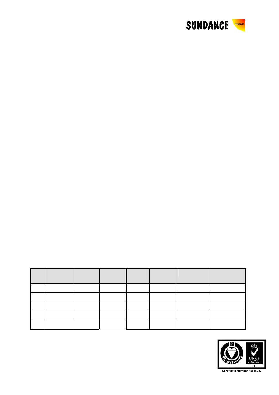
The following table shows connector pin-out and cable pair connections. This is
important, as the critical signals must be paired with a ground as shown. The
allocation to twisted pairs is based on grouping the data signals because they change
at the same time, so that crosstalk is not an issue. Each control signal has its own
ground:
Pin
Twisted
Pair
RTI
Signal
RTO
Signal
Pin
Twisted
Pair
RTI Signal
RTO Signal
1 1
I/O_OUT
I/O_IN
15 8
D2
D2
2 1 GND
GND 16 8
D3
D3
3 2 I/O_IN
I/O_OUT
17 9
D4
D4
4 2 GND
GND 18 9
D5
D5
5 3
/CSTRB
/CSTRB
19 10
D6
D6