Comports, Figure 1: comport connection diagram, 7 comports – Sundance SMT410 v.1.0 User Manual
Page 15
User Manual (QCF42); Version 3.0, 8/11/00; © Sundance Multiprocessor Technology Ltd. 1999
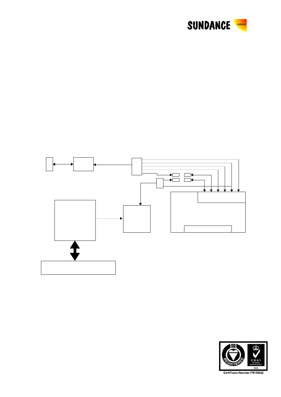
7 ComPorts
The SMT410 gives access to all six TIM site ComPorts. One of four ComPorts can be
connected through a high drive buffer to a connector on the rear panel of the card.
This connection and switching is achieved using Quick switches alleviating the need
for patch cables.
Two of the TIM site ComPorts are connected straight to 14-way surface-mount FMS
connectors for connection to other ComPort compatible devices within the same
chassis.
There is a connection from the PCI interface to ComPort 3 for booting the TIM. This
connection can be severed with a quick switch (clear
CENc )
allowing ComPort 3 to be
used for other purposes. This also allows the PCI interface ComPort to be used
independently of the TIM as it is also wired to a 14-way surface-mount FMS
connector.
Buffer
PCI Bridg e
PCI Connec tor
Comm -
port
CPLD
Module Site
Buffered
Com m Port
Comm -ports
Global Bus
1
4
0
2
3 5
FMS
FMS
FMS
FMS
Quic k
Switch
Quic k
Switch
J4
J2
J3
J1
Figure 1: ComPort connection diagram
The configuration of the ComPorts on the SMT410 can be set using the ComPort
configuration register (I/O Offset 0x20).
Default = 0x2C (Assuming no FMS cables connected)