Sundance SMT410 v.1.0 User Manual
Page 17
Page 17 of 49
SMT410 User Manual V1.0
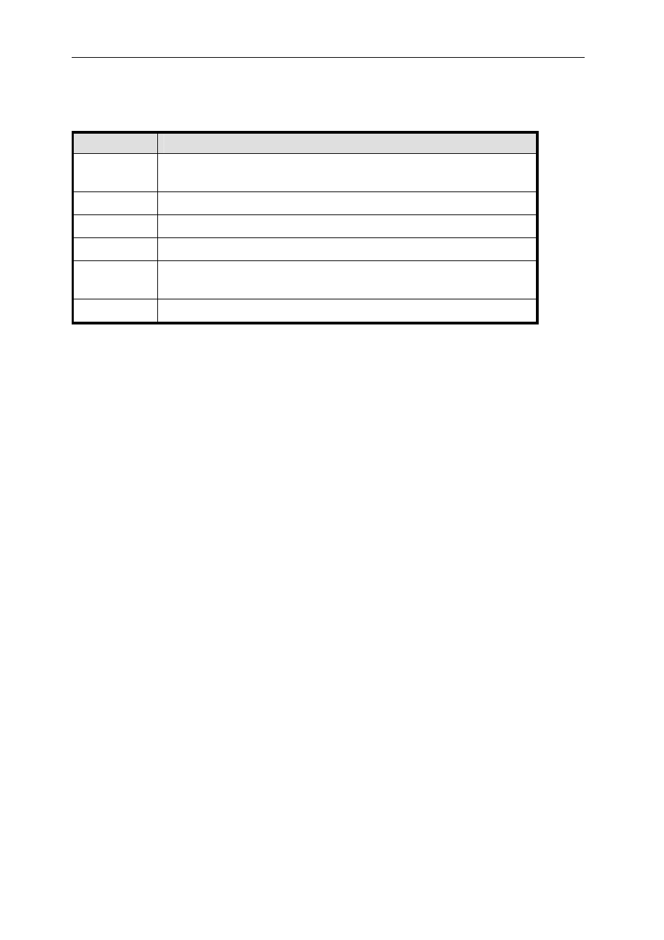
As well as the 12 C4x ComPort signals and signal grounds, there are 6 additional
signals. Note that these signals are NOT essential for communications:
Name
Description
I/O_OUT
Output high when port is outputting data, output low when
port is receiving data.
I/O_IN
Input which prevents bus contention if connected to I/O_OUT
/RST_OUT
Active low open collector copy of the board reset drive.
/RST_IN
Active low board reset input, pulled up to 3.3V by 100 ohms.
VCC
1 AMP +5 Volt supply, with resettable 1 Amp fuse, to power a
remote buffer, if required.
SHIELD
Overall cable shield, connected to plug shells and chassis.
The /RST_OUT is intended to allow synchronised reset of a number of boards by
driving the /RST_IN input.
The ComPort configuration register controls the way in which the quick switches
route the TIM site ComPorts to the buffer (see table 4). There is also an overall
enable bit CENb that must be set to enable the quick switches.