Jtag/boundary scan – Sundance SMT498 User Manual
Page 32
JTAG/Boundary Scan
The JTAG header is provided to enable device programming via suitable software.
(See board header table for JTAG pin details). Typically, this will be Xilinx iMPACT.
Xilinx iMPACT supports Parallel Cable IV download cable for communication
between the PC and FPGA(s).
The JTAG header on the board was designed to mate directly with the 2mm
ribbon cable provided with the MultiLINX Cable IV. BE SURE TO ATTACH
THE RIBBON CABLE PROPERLY.
To directly configure the FPGA via the JTAG, remove the jumper near the PROM
chip as shown on the picture below. Turn switch 1 of S2 to ‘ON’ position and switch 2
of S2 to ‘OFF’ position. The switch 4 of S3 should be in ‘OFF’ position for the JTAG
to work.
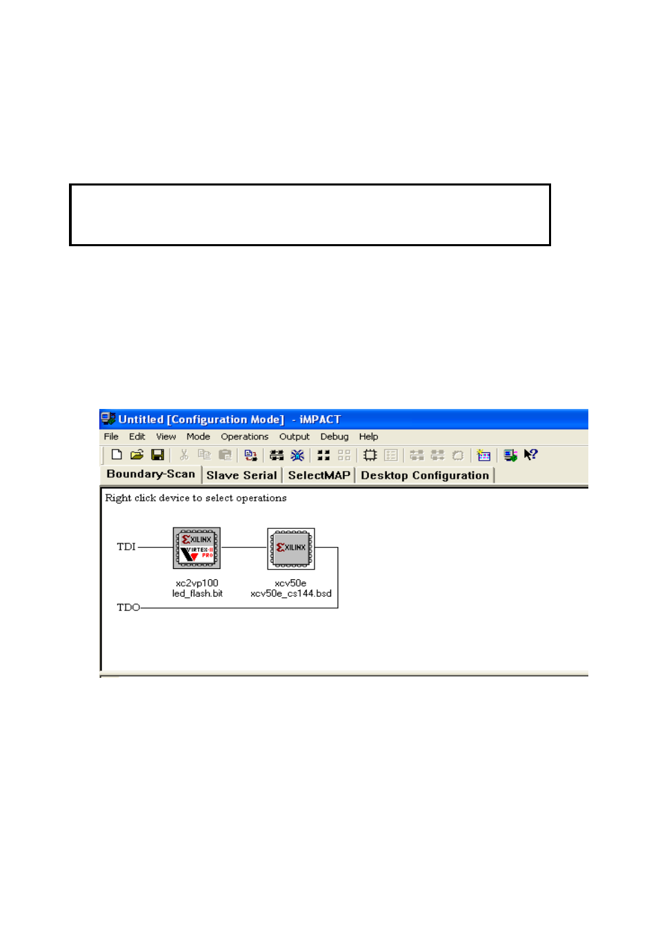
To initialize the JTAG chain, connect the Xilinx Parallel cable to JTAG IN connector
JA2. Using the Xilinx impact software initialize the JTAG chain, this will show two
devices as shown in the figure below
The first device will be the XC2VP100 and the second device will be XCV50E.
Assign the intended .BIT file to the XC2VP100 and program it. This will configure the
FPGA directly via the JTAG. To test the approaches please use the LED_FLASH.bit,
which is provided.
Page 32