Shbs, Table 5 – pmc p13/p14 interface – Sundance SMT498 User Manual
Page 24
39 VIO
AD44
40
39 I/O
I/O
40
41 AD43
AD42
42
41 I/O
I/O
42
43 AD41
GND
44
43 I/O
I/O
44
45 GND
AD40
46
45 I/O
I/O
46
47 AD39
AD38
48
47 I/O
I/O
48
49 AD37
GND
50
49 I/O
I/O
50
51 GND
AD36
52
51 I/O
I/O
52
53 AD35
AD34
54
53 I/O
I/O
54
55 AD33
GND
56
55 I/O
I/O
56
57 VIO
AD32
58
57 I/O
I/O
58
59 PCI-RSVD
PCI-RSVD
60
59 I/O
I/O
60
61 PCI-RSVD
GND
62
61 I/O
I/O
62
63 GND
PCI-RSVD
64
62 I/O
I/O
64
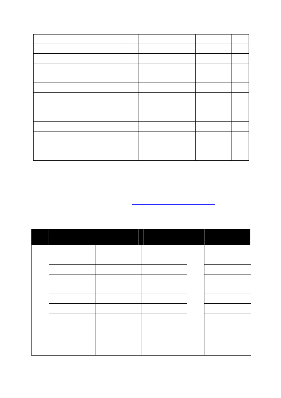
Table 5 – PMC P13/P14 Interface
SHBs
The SHB signals have been named to match 2 16-bit SDB interfaces (or Hw SHB
interface) pinout according to the
SUNDANCE SHB specification
Half Word
configuration. SMT498 will be equipped with 4 SHBs. Two SHBs will be wired to the
FPGA to support LVDS.
Hw
QSH Pin
number
QSH Pin
number
Hw
SHBxCLK0 1
2
SHBxD0(0)
SHBxD0(1) 3
4
SHBxD0(2)
SHBxD0(3) 5
6
SHBxD0(4)
SHBxD0(5) 7
8
SHBxD0(6)
SHBxD0(7) 9
10
SHBxD0(8)
SHBxD0(9) 11
12
SHBxD0(10)
SHBxD0(11) 13
14
SHBxD0(12)
SHBxD0(13) 15
16
SHBxD0(14)
SHBxD0(15) 17
18
SHBxUSER0(1
6)
Hw0
SHBxUSER0(1
7)
19 20
Hw0
SHBxUSER0(1
8)
Page 24