Inserts – Studio Technologies 58 2000 User Manual
Page 12
Model 58/59 User Guide
Issue 4, December 2000
Studio Technologies, Inc.
Page 13
for Surround
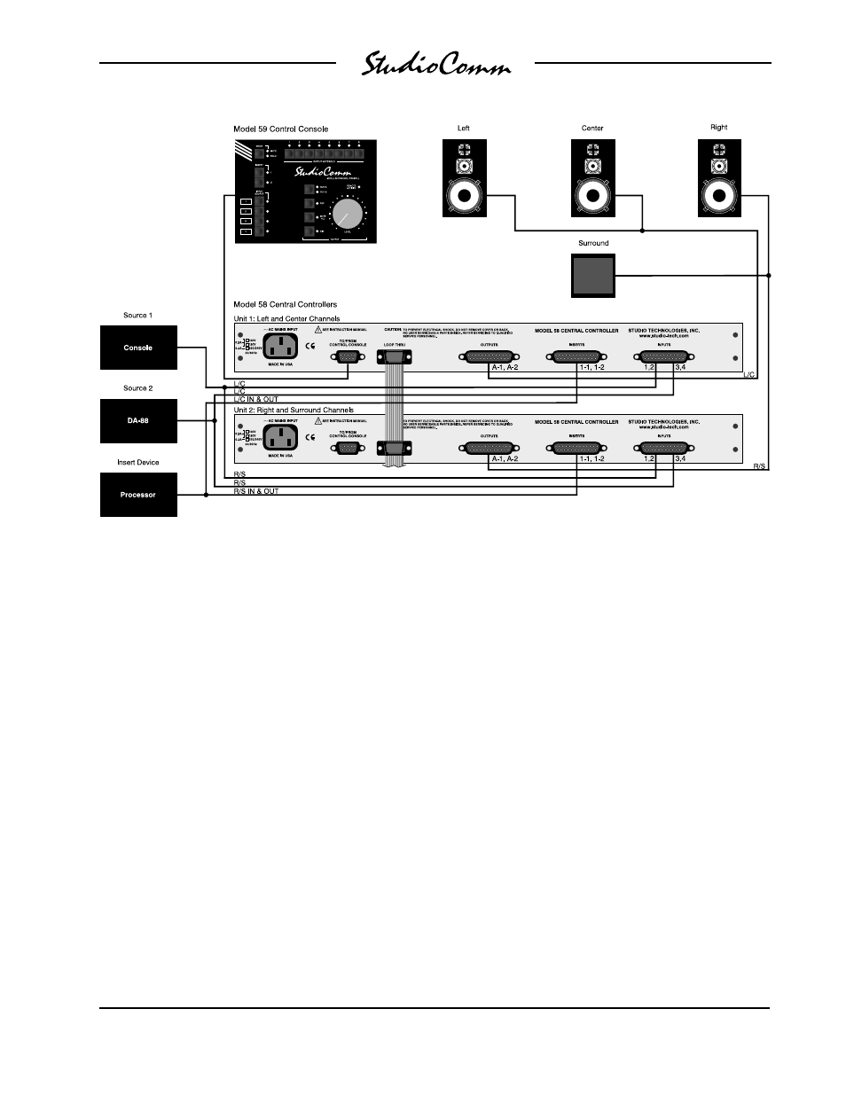
4-Channel (LCRS) Configuration
Figure 6 shows a 4-channel installation
that follows a traditional LCRS format:
Left, center, right, and surround. Again,
two 4-channel sources are connected,
along with one set of amplified loudspeak-
ers. The left and center channels are
supported by Model 58 unit 1, while the
right and surround channels are supported
by Model 58 unit 2. A processor device is
connected to one of the insert sections on
both Model 58 units. Two input, two insert,
and two output wiring harnesses are
utilized for audio interconnection.
The Model 59 Control Console is con-
nected to Model 58 unit 1, and both Model
58s are interconnected using a ribbon
cable bus assembly. AC mains power
must be connected to both Model 58 units.
Many features are available for future use,
including inputs 3 and 4, the second insert
section, monitor output B, the meter out-
puts, the bypass inputs, and the remote
control functions.
Inserts
The Model 58 insert sections are applic-
able for far more than the usual console-
provided insert functions. Under control
of the Model 59 Control Console, each
channel of each insert section can indepen-
dently function in one of four modes: Mute
the normal signal flow, maintain the normal
signal flow, replace the normal signal with
the return signal, or sum (combine) the
return signal with the normal signal. (Note
that in all cases the insert send signal will
remain active.) With this flexibility the
inserts can be used for a variety of insert,
routing, and mixing functions.
Figure 6. Example of 4-Channel (LCRS) Configuration