Advanced operation, Adjusting the line input trim pots – Studio Technologies 230 2014 User Manual
Page 33
Model 230 User Guide
Issue 9, November 2014
Studio Technologies, Inc.
Page 33
or both of the talkback-to-intercom func-
tions are configured for use the sidetone
trim pots associated with them should be
set for minimum sidetone level. This is
accomplished by adjusting the trim pots
to their fully counterclockwise positions.
This will minimize the level “build up” that
would occur when both the internal and
the intercom-releated sidetone audio is
being sent to the headphone output. The
goal is for the sidetone level to remain as
constant as possible, no matter what func-
tion (main output, talkback-to-line-level-
output, or talkback-to-intercom) is active.
Advanced
Operation
Adjusting the Line Input
Trim Pots
As has been previously mentioned, as-
sociated with the line inputs are trim pots
that allow the input levels to be adjusted.
The two trim pots are accessible by way
of round openings in the bottom of the
Model 230’s enclosure. By adjusting these
trim pots, signals with a nominal level
of –12 dBV to +6 dBu can be effectively
used as cue sources. Unfortunately, there
are no definitive rules regarding how best
to adjust the trim pots, but some sugges-
tions may prove to be valuable. Depend-
ing on how the line inputs are utilized, the
trim pots can be used to either adjust the
absolute level of each line input signal, or
to adjust the relative level of the signals
when compared to other sources. The
following examples may provide some
clarification.
Let’s begin with an application that has a
stereo cue source connected to the line
inputs. The source selection DIP switches
are configured to create a stereo head-
phone output with line input 1 assigned to
the left channel and line input 2 assigned
to the right channel. Begin the trim pot
adjustment process by moving the user
level controls (located on the front panel)
to their detent (50% of rotation) positions.
Then, with the stereo cue source provid-
ing signal at its normal level, adjust the
trim pots to provide a comfortable level
to the connected headphones. The user
can now, in response to changing condi-
tions, adjust the front-panel level controls
as desired. Returning the controls to their
detent positions will always provide the
“reference” level to the headphone output.
A second example has the IFB input and
line input 1 both providing cue sources.
Channel 1 of the IFB circuit supplies pro-
gram-with-interrupt audio that is routed
to the headphone output’s left channel.
Channel 2 of the IFB circuit supplies
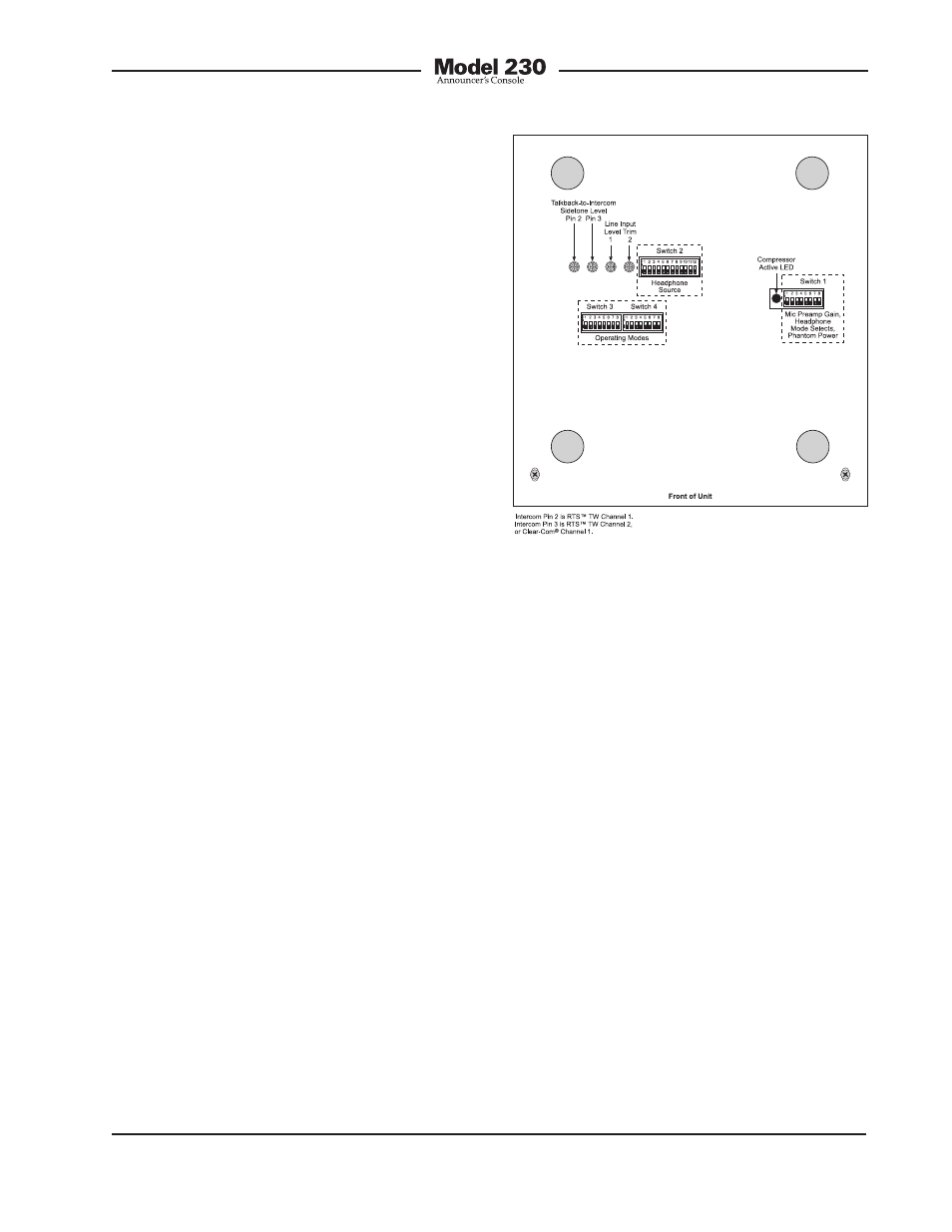
Figure 21. Bottom view showing line input and
talkback-to-intercom sidetone trim pots