Operating modes, Headphone output—right channel status – Studio Technologies 230 2014 User Manual
Page 22
Issue 9, November 2014
Model 230 User Guide
Page 22
Studio Technologies, Inc.
Operating Modes
The sixteen switches associated with
switch assemblies SW3 and SW4 are
used to configure the Model 230’s operat-
ing modes. Technically, these switches
“talk” to the microcontroller integrated
circuit and associated software that give
the Model 230 its “smarts.” The software
has been carefully designed to provide
a number of different ways in which the
unit can function. It’s critical to carefully
review the available options and choose
the ones that best meet the needs of a
specific application. Note that switches
can be changed even while the Model 230
is powered up and operating. The unit’s
operating characteristics will change in
“real-time” in response to configuration
changes.
Main Output Button Mode
Switches SW3-1 and SW3-2 configure
how the main output button functions.
There are four available modes:
• Push to mute: In this mode the main
output is normally active. The main
output will mute whenever the button
is pressed and held. This is the “cough”
mode typically used for on-air sports
broadcasting applications.
• Push to talk: In this mode the main out-
put is normally muted. The main output
will become active whenever the button
is pressed and held.
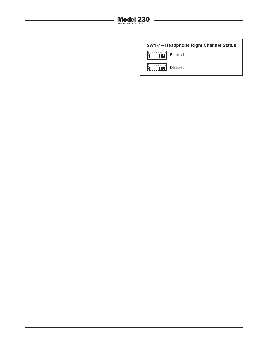
Figure 8. Headphone output—right channel
status settings
There is one limitation related to the head-
phone output mode. It’s the fact that the
output will be 2-channel monaural. What-
ever signal is present on the headphone
output’s left channel will also be present
on the right channel. (The exception is if the
right channel output is disabled using the
DIP switch setting.) A stereo headphone
mix can’t be created. But in most cases this
limitation won’t overshadow the benefit of
being able to create the mix. For signal-flow
clarification please review the block diagram
located at the end of this user guide.
Headphone Output—Right
Channel Status
Switch SW1-7 allows the right channel of
the headphone output to be disabled. This
is provided for applications where monaural
headsets or headphones are going to be
connected. In general, monaural devices
use 2-channel (tip and sleeve) ¼-inch plugs.
When inserted into the Model 230’s stereo
(3-conductor) headphone output jack the
right channel, electrically connected to the
jack’s ring lead, will be shorted. While this
condition should not damage the output
circuit, it will cause current to flow unneces-
sarily. To minimize this possibility disable
the right channel output by placing switch
SW1-7 to its on position.
It’s important to note that the circuitry that
disables the right channel is electrically just
prior to the right channel output circuit. It
is after (“post”) all other circuitry, including
the source assignment DIP switch, level
controls, and monaural function. It will not
impact normal use of the other functions,
including the ability to create the special
“2-channel headphone mix” mode previ-
ously discussed. For signal-flow clarification
please review the block diagram located at
the end of this user guide.