Microphone preamplifier gain and phantom power – Studio Technologies 230 2014 User Manual
Page 18
Issue 9, November 2014
Model 230 User Guide
Page 18
Studio Technologies, Inc.
Refer to Appendix A for a representative
view. The security plate is held in place by
means of four rubber bumpers (“feet”) that
have built-in screws. Using your fingers,
remove the four bumpers so that the plate
can be removed. Refer to Figure 3 for a
detailed view of the configuration switch
assemblies.
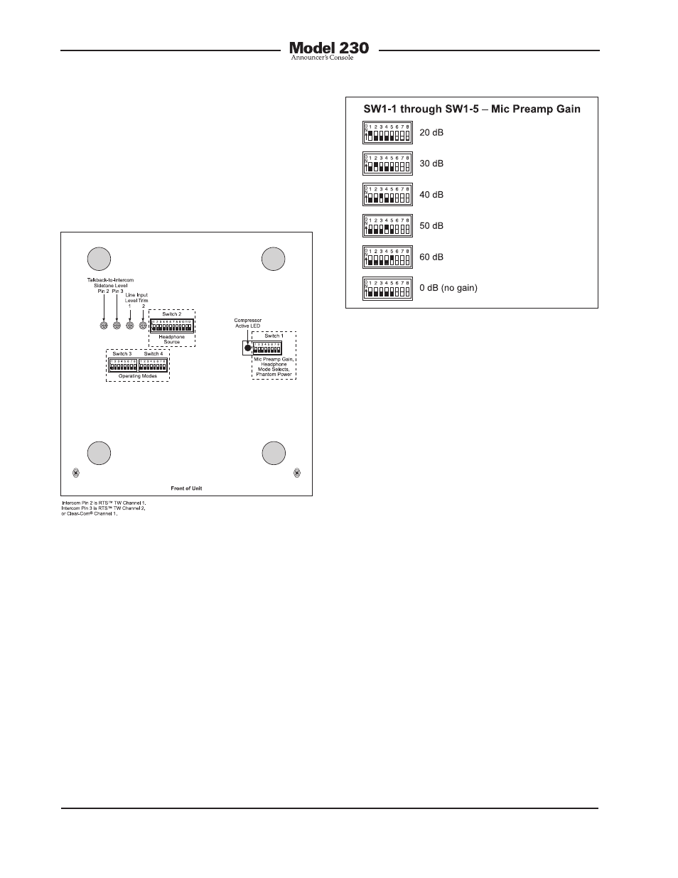
Figure 3. Bottom view of Model 230 showing
configuration switches, trim pots, and
compressor active LED
time. There’s no problem changing the
gain setting while the unit is operating.
Audio clicks or pops might occur during
gain transitions, but this shouldn’t be a
major issue as long as associated monitor
loudspeakers are temporarily attenuated
or muted.
Selecting the correct amount of gain for
an application might take a little experi-
mentation. The goal is to bring the mic’s
signal up to line level, nominally –2 dBu for
the Model 230’s main output. Operating
at this signal level will help to ensure the
delivery of “clean” audio to the connected
device. It’s also acceptable to connect a
live-level audio source to the microphone
input. In this case selecting 0 dB (no gain)
would be appropriate.
The output of the Model 230’s microphone
preamplifier is used by the main output
and, by way of the compressor circuit, the
talkback outputs. So creating a nice “hot”
signal will help maintain audio quality, spe-
cifically a high signal-to-noise ratio, when
driving the often-lengthy cable runs.
Microphone Preamplifier Gain
and Phantom Power
Five switches are used to set the gain of
the microphone preamplifier. One switch
is used to select the on/off status of the
phantom power supply.
Microphone Preamplifier Gain
Switches SW1-1 through SW1-5 are used
to select the gain of the microphone pre-
amplifier. The choices are 20, 30, 40, 50,
60 dB; 0 dB (no gain) is also available.
Only one switch should be enabled at a
Figure 4. Microphone preamplifier gain switch
settings