Headphone output mode – Studio Technologies 230 2014 User Manual
Page 21
Model 230 User Guide
Issue 9, November 2014
Studio Technologies, Inc.
Page 21
this would require that switches SW2-1,
SW2-8, and SW2-9 be placed in their on
positions.
Note that in some cases a user may wish
to wear a headset or a pair of headphones
in a left/right orientation opposite of what
is usual. In this situation the transducer
designated for the left ear would actually
supply audio to the user’s right ear, and
vice versa. A specific application where
this occurs is when on-air talent needs to
have a headset’s boom microphone come
across the right side of their face, rather
than the more-typical left side. In this case
it’s important to select the left- and right-
channel headphone source assignment
accordingly. With the Model 230’s flexible
source selection there’s no reason why
users, such as on-air talent, shouldn’t have
their cue sources assigned correctly.
Special applications may benefit from
using the Model 230 in a special “2-chan-
nel headphone output mixer” mode. This
is accomplished by first configuring the
headphone output to monaural. (Details on
how to accomplish this are described later
in this section of the user guide.) Next the
cue source whose level is to be adjusted
by the rotary control on the left side of the
front panel is assigned to the left channel.
Finally, the cue source whose level is to be
adjusted by the right control is assigned to
the right channel. During operation the user
will create their desired cue mix using the
two front-panel controls.
There may also be cases where a monaural
“single-muff” headset or headphone will be
connected to the Model 230’s headphone
output. In this case the desired source
must be routed only to the left channel.
This is because the 2-conductor plug that’s
typically associated with a mono headset
or headphone will connect only to the tip
lead (left channel) of the headphone out-
put. Signals assigned to the right channel
will not be heard by the user.
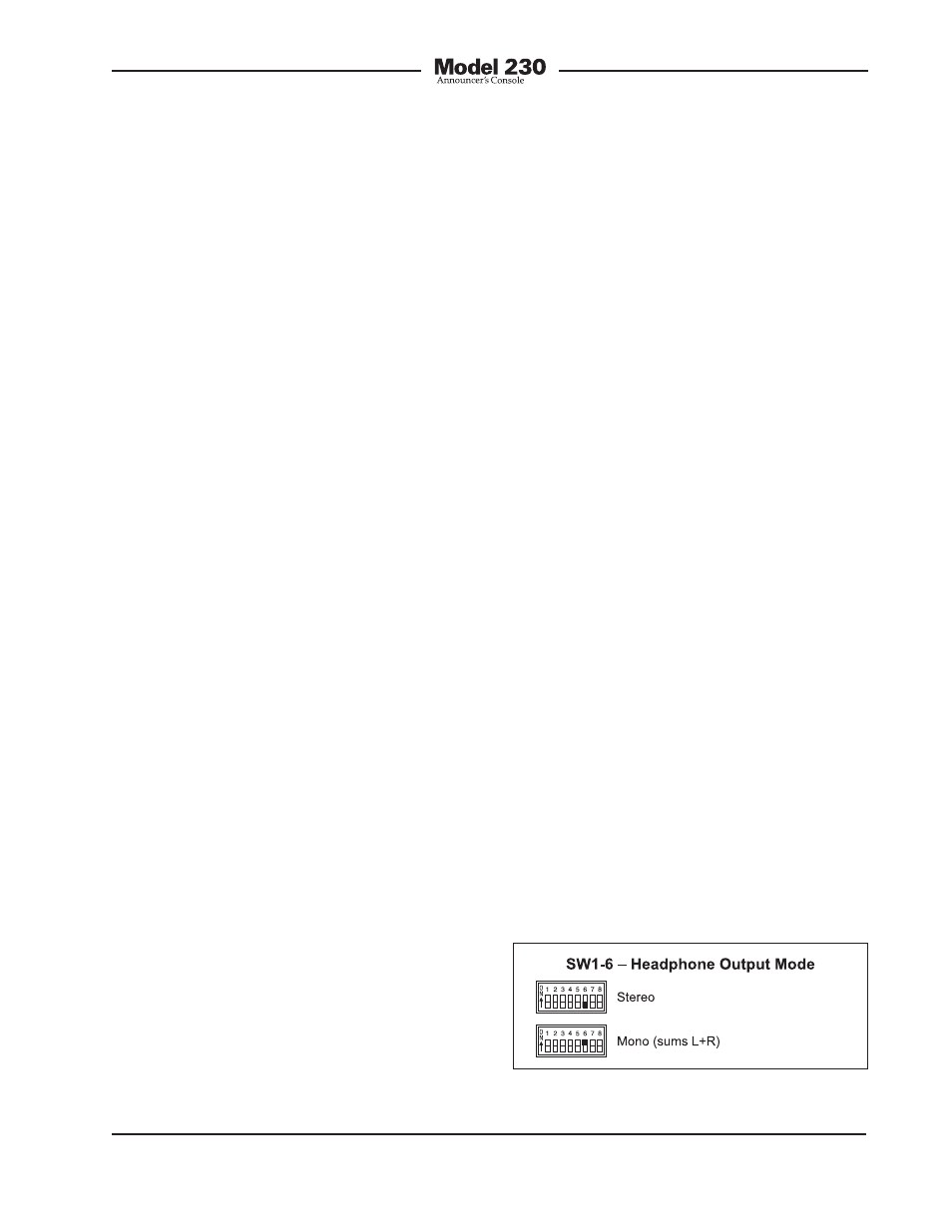
Headphone Output Mode
Switch SW1-6 allows a monaural head-
phone output to be created. This is ac-
complished by summing (adding) the
selected left- and right-channel cue sig-
nals. The combined signals are sent to
both the left- and right-channel headphone
output driver circuits. The outputs of these
circuits connect, by way of 100 ohm series
protection resistors, to the headphone
output jack.
The headphone output monaural mode
feature was specifically included so that
a special “2-channel headphone mix”
mode can be created. By enabling the
mono mode, the two front-panel user level
controls (“pots”) can be used to create
the desired “mix” of signals being sent
to the headphone outputs. Many, many
applications, especially in production set-
tings, can benefit from this capability. The
desired cue sources must be carefully as-
signed to take advantage of the monaural
mode. The first cue source should be as-
signed, using the DIP switches, to the left
channel. Its output level will be adjusted
by the left control. The second cue source
should be assigned to the right channel.
Its output level will be adjusted by the right
control.
Figure 7. Headphone output mode settings