3) air switch pressure check, 4) ignition system checks – Space Ray ETS Series User Manual
Page 52
Form 43343300
May 2013
-51-
24.3)
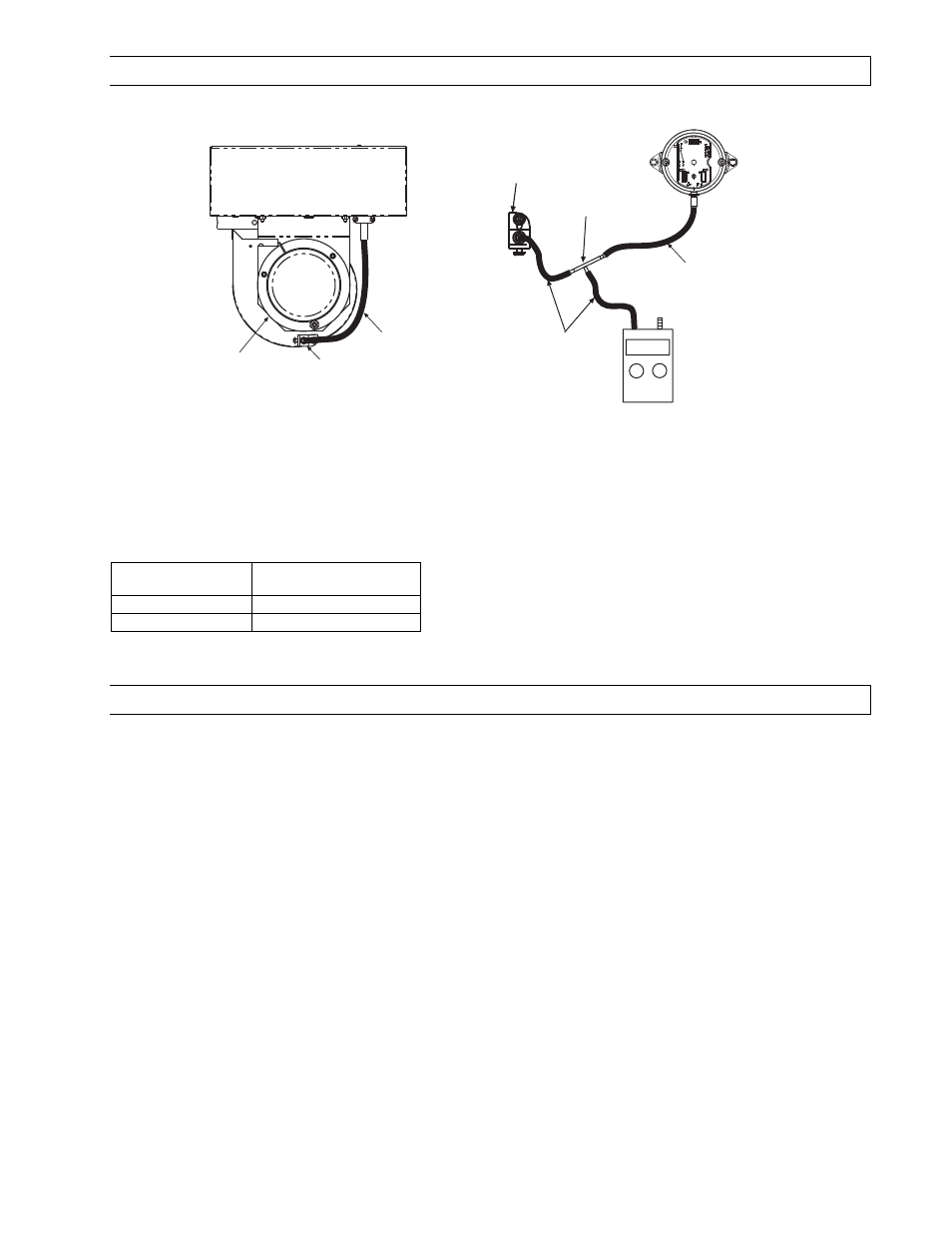
AIR SWITCH PRESSURE CHECK
0.37 WC
+
-
Connector Tee
Digital or
Inclined Water
Manometer
scale 0-2w.c.
Temporary 1/4 ID
Silicone / plastic tubing
for pressure test.
Air Switch
(inside Junction Box)
Air sensing
tube bracket
Plastic Vacuum
Air Tube
Motor and Blower
Wheel Assembly
JUNCTION BOX
Plastic Vacuum
Air Tube
Air sensing
tube bracket
1.
Open hinged access panel.
2.
Add tubing to connect the air switch with the connector tee and the existing tubing.
3.
Connect plastic tubing of a digital or inclined water manometer with a 0-2” scale onto the connector tees.
4.
Turn heater on and wait until blower motor is activated.
5.
Observe air pressure from manometer. This should be higher than the set point indicated below for correct
operation.
Model
Model
Model
Model
Operating Pressure
Operating Pressure
Operating Pressure
Operating Pressure
ETS/U 40 - 175
0.42” W.C. Hot
ETS/U 180 - 250
0.57” W.C. Hot
All pressures are with the heater in operation for at least 15 minutes.
All pressures are with the heater in operation for at least 15 minutes.
All pressures are with the heater in operation for at least 15 minutes.
All pressures are with the heater in operation for at least 15 minutes.
24.4)
IGNITION SYSTEM CHECKS
TO CHECK
TO CHECK
TO CHECK
TO CHECK IGNITION CABLE
IGNITION CABLE
IGNITION CABLE
IGNITION CABLE....
a.
Make sure that the ignition cable does not touch any metal surface.
b.
Make sure that connections to the stud terminal and the igniter/sensor are clean and tight.
c.
Make sure that the ignition cable provides good electrical continuity.
TO CHECK
TO CHECK
TO CHECK
TO CHECK IGNITION SYSTEM GROUNDING
IGNITION SYSTEM GROUNDING
IGNITION SYSTEM GROUNDING
IGNITION SYSTEM GROUNDING....
(Nuisance shutdowns are often caused by a poor or erratic ground.) A common ground is required for the module,
igniter, flame sensor and main burner.
a.
Check for good metal-to-metal contact between the igniter bracket and the main burner.
b.
Check the ground lead from the GND (BURNER) terminal on the module to the igniter bracket. Make sure
connections are clean and tight. If the wire is damaged or deteriorated, replace it.
c.
Replace igniter/sensor with factory replacement part if insulator is cracked.
TO CHECK
TO CHECK
TO CHECK
TO CHECK SPARK IGNI
SPARK IGNI
SPARK IGNI
SPARK IGNITION CIRCUIT
TION CIRCUIT
TION CIRCUIT
TION CIRCUIT....
▲WARNING:
▲WARNING:
▲WARNING:
▲WARNING: The ignition circuit generates a 20,000 Volt open circuit and electrical shock can result.
a.
Check ignition cable.
b.
Check external fuse located inside the draft inducer junction box.
c.
Verify power (24V) at module input terminals and output terminal to gas valve.
d.
Replace spark module if fuse and power are OK.