0) attaching draft inducer assembly – Space Ray ETS Series User Manual
Page 29
Form 43343300
-28-
May 2013
12.0)
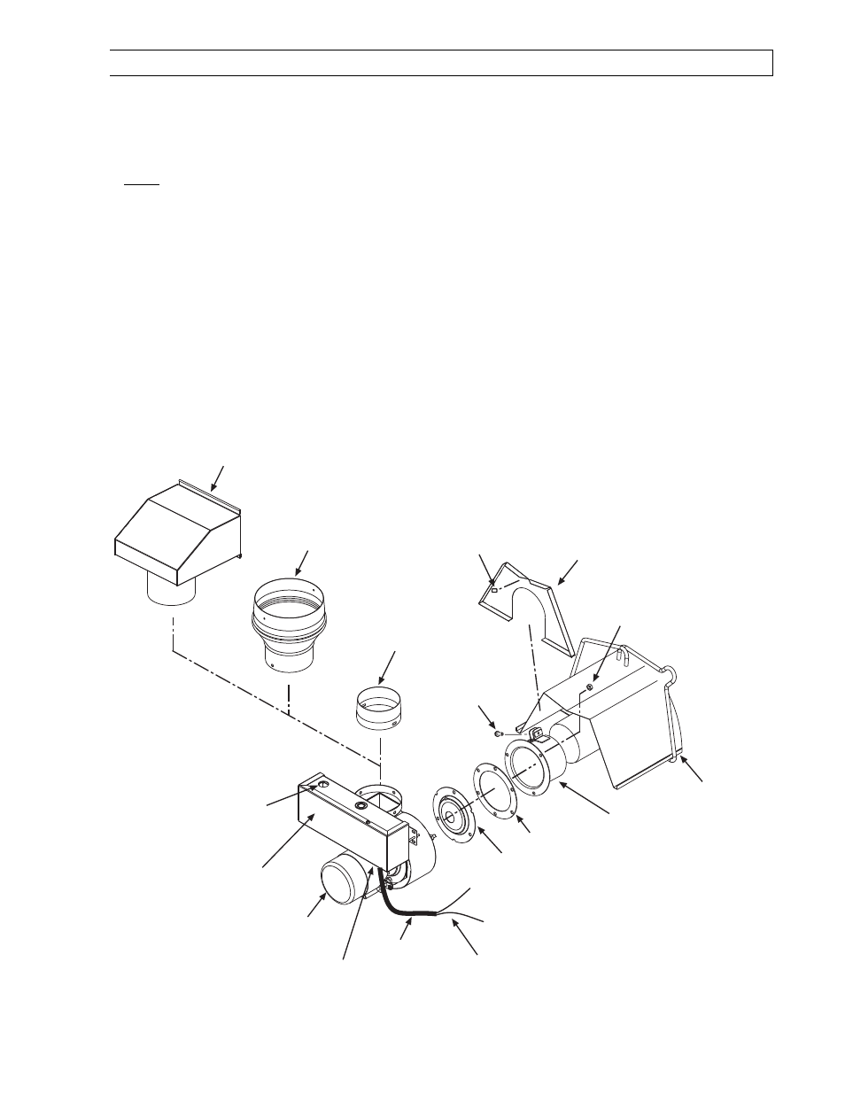
ATTACHING DRAFT INDUCER ASSEMBLY
1.
Slide the draft inducer flange over the end of tube. Rotate the flange until the tightening brackets are in the
upright position. Secure the flange by tightening the 1/4-20 screw located on the tightening brackets.
2.
Attach the draft inducer assembly and gasket to end of the draft inducer flange and secure with 1/4-20
locknuts. A flue restrictor plate is attached to the draft inducer weld studs. DO NOT DISCARD RESTRICTOR
DO NOT DISCARD RESTRICTOR
DO NOT DISCARD RESTRICTOR
DO NOT DISCARD RESTRICTOR
PLATE
PLATE
PLATE
PLATE and make sure this remains in place while the draft inducer is being attached to the heater body.
NOTE:
NOTE:
NOTE:
NOTE: The draft inducer can be mounted in a vertical, a 45º, or a horizontal position. Refer to Section 13.0).
3.
The 3/8" connector used to hold the SJO cable will remain to provide strain relief for field wiring of the
control box and the draft inducer (refer to the Electrical Connections and Connection Wiring Diagram for
wiring between the control box and the draft inducer in Section 16.0).
4.
If the heater is to be VENTED to the outside of the building, place the starting collar on the outlet of the draft
inducer and secure with the #8-32 screws and nuts. Place the flue pipe directly onto the starting collar,
secure with the #8 sheet metal screws, and terminate with an approved vent cap.
5.
If the heater is for UNVENTED use, place the exhaust hood (supplied as an accessory) directly onto the outlet
of the draft inducer (starting collar is not necessary for unvented use). Secure with the #8 sheet metal
screws. The exhaust hood must be mounted only in an upright position and directed toward the reflector
The exhaust hood must be mounted only in an upright position and directed toward the reflector
The exhaust hood must be mounted only in an upright position and directed toward the reflector
The exhaust hood must be mounted only in an upright position and directed toward the reflector
body.
body.
body.
body.
6.
Assemble the end reflector (optional on ETS/ETU series) flush with the end of the main reflector. Secure by
sliding speed clips onto the reflector edges. Evenly space the speed clips on the sides (one each side) and
top (two required) of the reflectors to provide a snug fit. Leave a 3” space between the end reflector and the
draft inducer assembly.
Optional
End Reflector
Speed Clip
(QTY-4)
Heater Body
1/4-20 Locknut
(QTY-3 per flange)
Draft Inducer
Flange
Note: The wiring connection
diagram is located on the inside
access panel and inside the
junction box panel.
Tube Flange
Gasket
Exhaust Hood
-Required for UNVENTED use-
4 x 6 Flue Pipe
Starting Collar
(for 180-250m BTU units only)
Flue Restrictor
Plate
Opening for
Electrical
Connection
(120V Power
Supply)
Junction
Box
Draft Inducer
24V Wire Leads
(to L1 and L2 of the
control box terminal
block)
4 Dia. Flue Pipe
Starting Collar
(for 40-175m BTU units only)
SJO Cable
3/8
Connector
1/4-20 x 1
Screw