Typical assembly overview (etu 40ft shown) – Space Ray ETS Series User Manual
Page 20
Form 43343300
May 2013
-19-
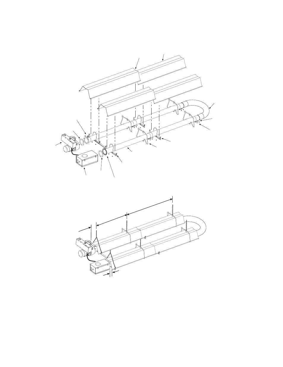
Typical Assembly Overview
(ETU 40FT Shown)
8 - 10
6 hanging points to be used for suspension. There
must be two hanging points on the first tube and one
on each of the other tubes
Maximum 6 distance
from control box &
draft inducer to first
tube support/hanger
bracket.
8 - 9 ¼
Wire Hanger
Draft Inducer
Assembly
#10 Self-Drill Screws
(Typical all tube supports
and tube couplings.)
4"OD x 10Ft.
See sections 7.0 & 7.2
for required tubes.
13 Tube Support Brk.
with U-Bolt Clamp
& 5/16" Hex Nuts
Tube Flange
12 Radial Hole for 40-200M BTU units only
6 Hole for 225-250M BTU units only
Gasket
Control Box
Gasket
Typical
Overlap
U-Bend
(accessory)
Tube Coupling
(Typical each tube joint.)
Reflector
31 Tube Support Brk.
with U-Bolt Clamp
& 5/16" Hex Nuts
Draft Inducer
Flange
3
(control to reflector)