Controls & instruments – Smithco Spray Star 1607P (1999) Operator Manual User Manual
Page 12
10
Introduction
CONTROLS & INSTRUMENTS
(
CONTINUED
)
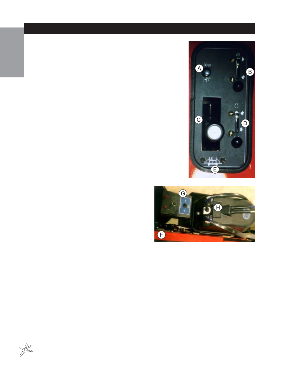
CONTROL PANEL
Located on right side of seat. The following are located on or near the con-
trol panel.
A. Choke: Pull out choke when starting cold engine, push in when
engine starts.
B. Ground Speed: Ratchet lever with a scale of "1-10", 10 is the
fastest, 0 is the slowest. The Ground speed control is a device that
limits the accelerator movement at the engine. Its purpose is to
provide the operator with the ability to maintain a constant ground
speed (predetermined) by the full depression of the accelerator
pedal.
C. Shift Lever: Gear selection, with the shift pattern on the shift
knob.
D. Hand Throttle: This hand throttle is used for hose/handgun
spraying, boom spraying and sprayer calibration. It controls engine
RPM, forward for fast, opposite direction for slow. (Not to be used
when in motion).
E. Right and Left Boom Switches: These toggle switches are used
to raise and lower the right and left electric actuated booms.
FOAM MARKER CONTROLS
F. Park Brake: Push to the front and down to set
park brake and pull back to release. Some
adjustments can be made to park brake by
turning knob on the of the lever. To tighten, turn
knob clockwise. To loosen turn counter clockwise.
G. Foamer ON/OFF Switch: Located to the right of
the control panel. Used to turn on and off the
foam marker. Also, used to designate which
boom is to be used to dispense foam. With lever
pointing toward the seat foam will dispense from
right boom, and with lever pointing forward foam
will dispense from the left boom.
H. Foamer Adjustment Knob: Located behind the seat on the right side on top of the foamer. Use this
knob to adjust pressure of the foam that will be dispensed.
ELECTRONIC SPRAY CONTROL SYSTEM
Pressure must be set with sprayer in operation (booms on). Increase pressure by pushing the pressure adjust-
ment handle upwards. Once the console reaches maximum pressure, the motorized control valve in the
sprayer then begins to open and pressure begins to decrease. Push switch in either direction until desired pres-
sure is reached. The system provides operation of one, two or three booms and it controls sprayer pressure
indicated by a wet pressure gauge on the vehicle. The pressure gauge reads the pressure in psi. The control
system is operated by the 12 volt electrical system of the vehicle. The master switch controls all boom
switches. Boom switch #1 controls left boom, boom switch #2 controls center boom, and boom switch #3 con-
trols right boom. Pressure switch increases or decreases spraying pressure through the motorized control
valve.