005 hydraulic sand plow instructions, Front attachment – Smithco Sand Star I 45-001 Parts & Service Manual User Manual
Page 78
A-7
Front Attachment
45-005 HYDRAULIC SAND PLOW INSTRUCTIONS
1. Assemble Pusher Bars (Ref # 11 and 12) to Plow Blade (Ref # 5) using one
3
/
8
-16 x 1 Bolt (Ref # 9) and
one
3
/
8
-16 x 3 Bolt (Ref #10) per Pusher Bar. There are 2 holes to bolt (Ref # 9) hardware in. Using hole
closest to the blade will result in a shallow cut, whereas using the hole furthest from the blade will result in
a deeper cut. The slot on the pusher bar is for a more fine tuned adjustment.
2. Assemble the Ram Mount (Ref# 1) to the Main Frame using the two studs that are welded to the frame
and below the front of the console.
3. Using a ½ x 1½ Clevis Pin (Ref # 2) and
1
/
8
x 1 Cotter Pin (Ref #3) mount the Hydraulic Cylinder (Ref # 4)
to the Lift Assembly . Connect the other end of the Hydraulic Cylinder to the Ram Mount using ½ x 1½
Clevis Pin (Ref # 2) and
1
/
8
x 1 Cotter Pin (Ref #3).
4. Slide the Plow/Pusher Bar Assembly under machine and connect to machine. Secure using ½ x 1½
Clevis Pins (Ref # 2) and
1
/
8
" Bridge Pins (Ref # 12).
5. Thread four 45° Elbow fittings (Ref # 16) into the Single Bank Valve (Ref # 17), one each in the A port, B
port, IN port and OUT port. Thread two
3
/
8
Straight Thread Elbow fittings into the ports on the Hydraulic
Cylinder (Ref # 4). Make sure the fittings on the Hydraulic Cylinder are pointing towards the machine.
6. Connect the 57½" Hose (Ref # 23) to the IN port on the Single Bank Hydraulic Valve (Ref #17). Connect
the 75" Hose (Ref # 20) to the OUT port. Next connect the 18"
Hose (Ref # 21) to the fitting in the B port and connect the 20"
Hose (Ref # 22) to the fitting in the A port.
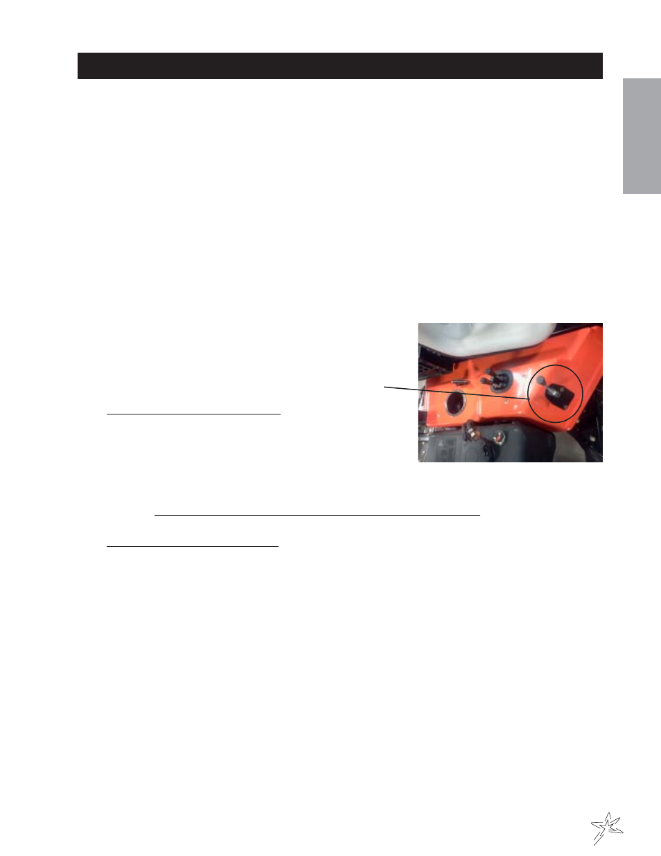
7. Mount the Single Bank Hydraulic Valve (Ref # 17) to the Valve
Mount (Ref # 15) as illustrated, using the two ¼ - 20 x 2 Bolts
(Ref # 12). Secure with the two ¼ - 20 Flange Whiz-Lock Nuts.
Connect the Straight Handle (Ref # 18) to the Valve. Reference
Single Bank Hydraulic Valve Drawing for a detailed view of the
Valve.
8. Route the 18" Hose (Ref # 21) from the B port on the Single
Bank Hydraulic Valve to the rear port on the Hydraulic Cylinder.
Route the 20" Hose (Ref # 22) from the A port on the Single
Bank Hydraulic Valve to the front port on the Cylinder.
9. Disconnect the negative (-) ground battery cable from the battery. Place a drain pan under the valve on the
machine. ENGINE MUST BE COOL BEFORE DISCONNECTING THE HOSES.
10. Disconnect the hose from the OUT port on the 2 Bank Valve (Ref # 24) and the top port on the Oil Cooler.
Discard this hose, it will not be used. Connect the 75" Hose (Ref # 20) from the OUT port on the Single
Bank Valve to the top port on the Oil Cooler. Connect the other 57½" Hose (Ref # 23) from the IN port of
the Single Bank Valve to the OUT port of the 2 Bank Valve. Route the Hoses under the body and along the
frame avoiding any pinch points. Fasten to the frame using the 14½" Nylon Ties.
11. Reconnect the negative (-) ground battery cable to battery.
12. Make sure that everything is clear of the machine. Start the machine, work the valve so that the plow will
both raise and lower. Also, do this with both the attachment lift and the rake lift. Work the lift a number of
times until all air works out of the plow circuit and the cylinder works smoothly. At this time look for
hydraulic leaks. If there are leaks, turn engine off and repair, start up and check again.
13. Check the hydraulic oil level. The level should be 2” to 2½” below the top of the tank. If
more is needed, use SAE 10W-40 API service SG motor oil.