Fig#2, Run flat cable underneath phone – Skutch Electronics CK-1R3 User Manual
Page 2
Page 2 of 4
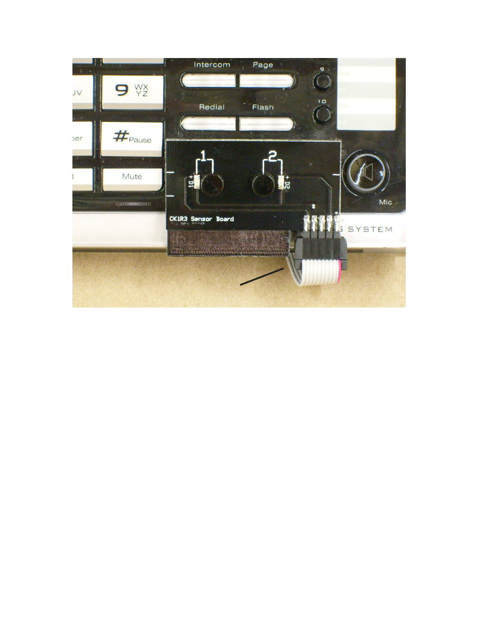
Run Flat Cable underneath phone
Sensor Board covers LINE 1
and LINE 2 Buttons. It fits
the contour of the phone.
Fig#2
3- Connect the supplied modular cord to [1&2 Phone] on CK-1, and the other end to the
jack [LINE 1+2] on the Phone.
4- Connect the RCA audio cord from the AUDIO IN jack on the back of the CK-1 box,
to your audio source. If your audio source has an 1/8” phone jack, use the audio adapter
on the end of the cable.
5- Run the Flat Gray Sensor Board cable underneath the base phone. Make sure that the
surface area of the base phone, where the sensor board is to be mounted, is clean and free
of all dust and oil film. Peel off the paper protectors from the bottom of the sensor board,
and carefully place it OVER the LINE 1 and LINE 2 buttons on the RCA phone as shown
in Fig #2.
6- Connect the POWER CUBE from the CK-1 BOX to 115VAC power. That's it!