Sensor board alignment – Skutch Electronics CK-1P5 User Manual
Page 2
Page 2 of 4
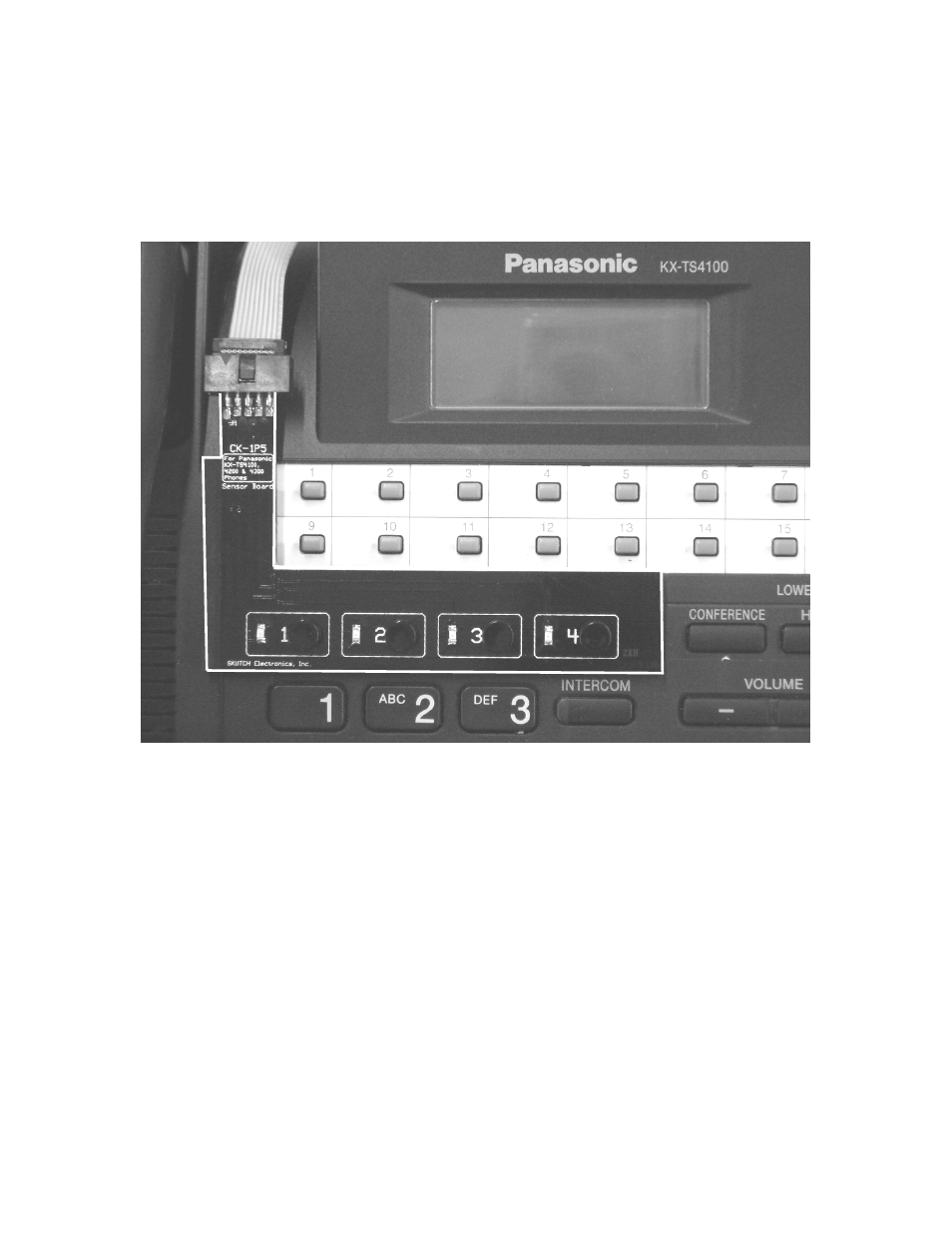
2- Peel the paper protector off back side of the "SENSOR BOARD" . Carefully align as
shown in the picture below. The Sensor Board will almost snap into place, as it is
designed to fit the contour of the phone. The Sensor Board will completely cover the
Line 1 through 4 buttons on the phone. The LEDS on the Sensor Board do NOT align to
the LEDS on the phone.
Sensor Board Covers Line
1-4 Buttons on Phone. It fits
the contour of the phone for
easy alignment.
Sensor Board Alignment
CAUTION: The SENSOR BOARD must be aligned correctly or the unit will not operate
properly. If you need to remove the SENSOR BOARD once it is attached, slowly lift up
on one edge of the SENSOR BOARD.
3- Position the CK-1 box under the base telephone with the jacks facing towards the back
of the phone. (See Fig. 3).
4- Connect the short modular cord from [1&2 to Phone] on CK-1 to [LINE 1/2] on
Phone.
5- Connect the short modular cord from [3&4 to Phone] on CK-1 to [LINE 3/4] on
Phone.
6- Connect the RCA end of the Audio cord, to the AUDIO IN jack on the back of the
CK-1 box. Connect the other end to your audio source. If your audio source has a 3.5mm
audio connector, use the supplied audio adapter on the end of the cable.
7- Connect a MOD cord from Telephone Wall Jack 1&2 to [1&2 to Line] on CK-1.
8- Connect a MOD cord from Telephone Wall Jack 3&4 to [3&4 to Line] on CK-1.
9- Connect the POWER CUBE from the CK-1 box to 115VAC power.