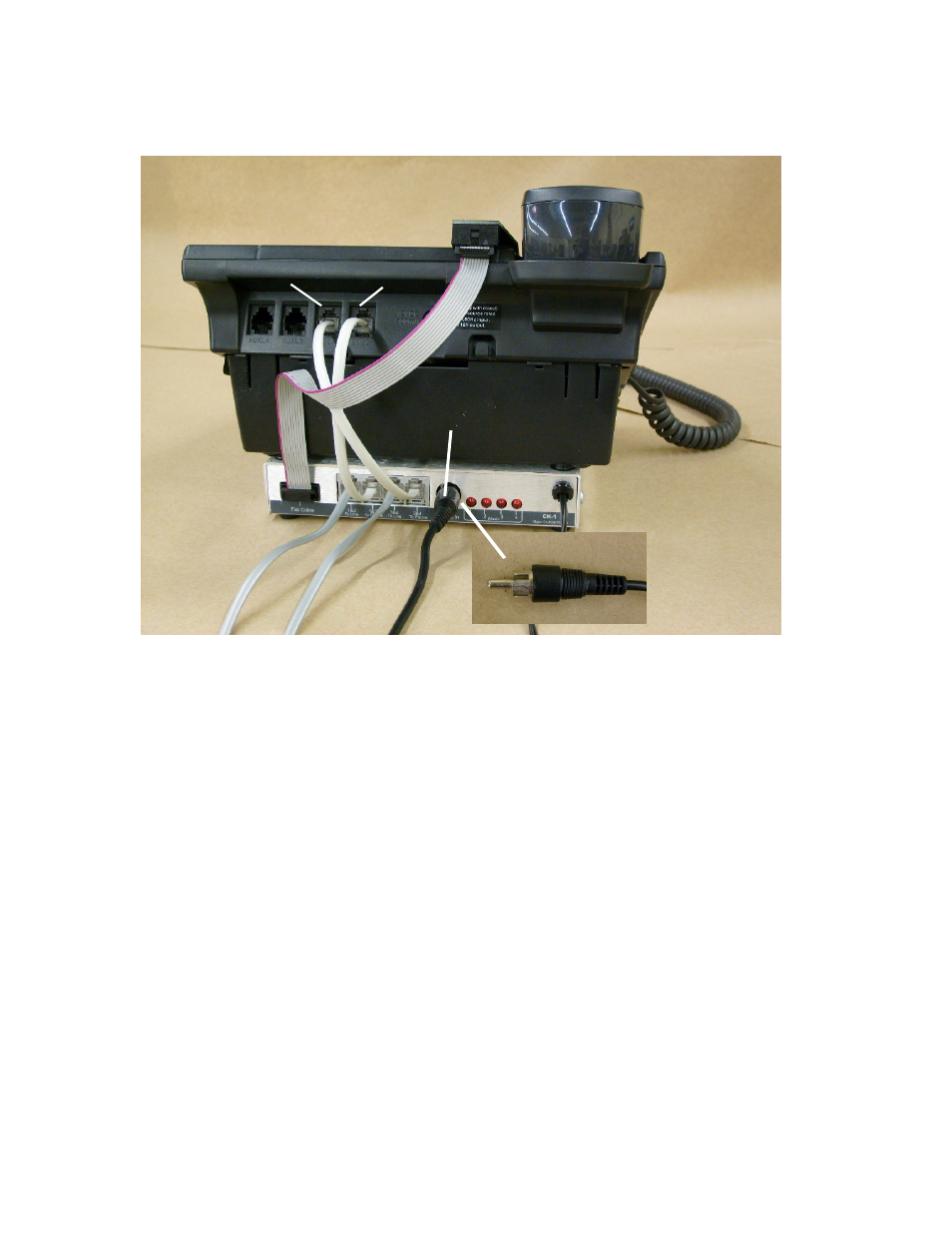
Fig #3, L1/l2 l3/l4 audio cable, Testing the system – Skutch Electronics CK-1A4 User Manual
Page 3
Page 3 of 4
Lines 1&2
Lines 3&4
L1/L2
L3/L4
Audio Cable
Fig #3
4- Connect the short modular cord from [1&2 to Phone] on the CK-1 to the [L1/L2] jack
on the Phone.
5- Connect the short modular cord from [3&4 to Phone] on the CK-1 to [L3/L4] jack on
the Phone.
6- Connect the audio cord from the AUDIO IN jack on the back of the CK-1 box, to your
audio source. If your audio source has a 1/8” phone jack, use the audio adapter on the end
of the cable. Do NOT use the Audio Adapter on the end that connects to the CK1A4 box.
7- Connect a MOD cord from Telephone Wall Jack 1&2 to [1&2 to Line] on CK-1.
8- Connect a MOD cord from Telephone Wall Jack 3&4 to [3&4 to Line] on CK-1.
9- Connect the POWER CUBE from the CK-1 box to 115VAC power.
Testing the System:
1- Pickup line 1 on your telephone. The line one GREEN LED on the SENSOR BOARD
should light up.
2- Repeat this test for lines 2-4. If all lines light up when picked up, the CK-1 is working
properly. If the lights on the SENSOR BOARD do not light up, then
a) Make sure that the CK-1 and Phone is connected to power.
b) Make sure that the SENSOR BOARD is aligned as shown in(Fig 2.