Sensoray 425 User Manual
Page 20
Sensoray Model 425 Instruction Manual
Page 18
Gain Programming
Digitizer gain may be set to unity or higher by means
of a programming resistor. All analog input channels
have the same gain.
Gain is programmed by installing a resistor at position
R8. The value of resistor R8 can be calculated for any
arbitrary gain using this formula:
To prevent thermally-induced gain errors, R8 should
have a low temperature coefficient — preferably 50
ppm/C or less.
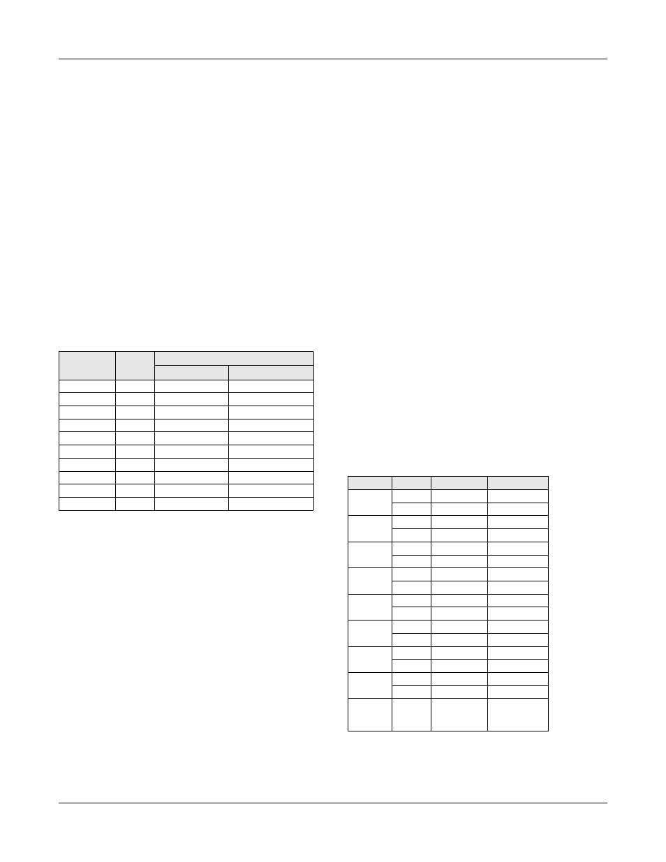
The table below shows required R8 values for various
gains using standard 1% resistor values. The listed gain
values are approximate and may be trimmed to exact
values as described in the next section.
As shipped from the factory, digitizer gain is set to
unity (R8 not installed).
Gain Trim
Digitizer gain may be trimmed by adjusting
potentiometer R1. This trimmer provides an adjustment
range of approximately percent.
Offset Trim
Digitizer offset may be trimmed by adjusting
potentiometer R2. This trimmer provides an adjustment
range of approximately . Since this adjustment
may alter circuit gain, offset should be trimmed before
adjusting gain.
R8
(ohms)
Gain
Input Range
Unipolar
Bipolar
Open
1
0 to +10V
-5 to +5V
49.9K
2
0 to +5V
-2.5 to +2.5V
12.4K
5
0 to +2V
-1V to +1V
5.49K
10
0 to +1V
-500 to +500mV
2.61K
20
0 to +500mV
-250 to +250mV
1.00K
50
0 to +200mV
-100 to +100mV
499
100
0 to +100mV
-50 to +50mV
249
200
0 to +50mV
-25 to +25mV
100
500
0 to +20mV
-10 to +10mV
49.9
1000
0 to +10mV
-5 to +5mV
R
49400
Gain
1
–
-------------------
=
7
±
6mV
±
Input Connections
Each analog input channel makes two connections to
the board as a differential pair. The digitizer measures
the voltage across any such pair.
Input common-mode voltage — the voltage at either
input relative to the ISAbus five volt return (GND) —
should not exceed volts. Minor excursions beyond
this limit may cause measurement errors. Significant
excursions may cause damage to digitizer circuitry.
Refer to the specifications for further details.
All analog input sources should be referenced to
ISAbus GND. If you are connecting an isolated source
(a source not referenced to GND), you should tie one
side of the source to GND. Since analog input channels
are differential pairs, it doesn’t matter which side is
connected to GND.
Connector Pinout
All analog inputs connect to connector P2. This
connector is shared by analog input and analog output
functions. The table below describes that portion of P2
related to analog input functions. Note that the GND
signals are related to both analog input and output
functions.
Connector P2: Analog I/O
Chan
Pin
Name
Function
0
2
ADC0+
+ input
4
ADC0-
- input
1
6
ADC1+
+ input
8
ADC1-
- input
2
10
ADC2+
+ input
12
ADC2-
- input
3
14
ADC3+
+ input
16
ADC3-
- input
4
18
ADC4+
+ input
20
ADC4-
- input
5
22
ADC5+
+ input
24
ADC5-
- input
6
26
ADC6+
+ input
28
ADC6-
- input
7
30
ADC7+
+ input
32
ADC7-
- input
33,34,
38,39,
40
GND
Analog
common
10
±