Selecting capture type for counters, Arming/disarming event capture, Monitoring captured events – Sensoray 425 User Manual
Page 11: Timer 00
Page 9
Sensoray Model 425 Instruction Manual
Event Detection
Each counter may be programmed to capture the occurance
of, and take special action in response to, a channel event.
The act of enabling captures is called “arming.” Before
arming a channel, the event types to be captured must be
selected. Two types of events may be captured: index and
rollover. Index events occur when the channel’s index
signal transitions to the active state, while rollover events
occur as described earlier under Rollovers.
Each counter is allocated an “Arm” control register for
enabling and disabling event capture, and two status flags,
“Capture” and “IndexCapture,” to log captured events.
These status flags are automatically reset when the channel
is disarmed.
When armed, a selected event will set the Capture flag. In
addition, captured index events will set the IndexCapture
flag, and may be programmed to automatically reset the
counter contents to zero.
New event captures are inhibited when the Capture flag is
set. To capture new events after a previous capture has been
processed, disarm the channel to clear the capture flags and
then re-arm the channel to enable new captures.
Selecting Capture Type for Counters
When operating as a counter, a channel may be configured
to capture an index, a rollover, or both. When operating as
a timer, a channel may be configured to capture a rollover
or both rollover and index, but not index only.
The event types to be captured depend on the channel
operating mode and the CM1 and CM0 Capture Mode bits
in the counter control port:
The CM1 and CM0 bits, which default to 00 upon soft or
hard board reset, are individually programmed by separate
write operations to the counter control port.
Arming/Disarming Event Capture
The Counter control port is used to arm and disarm event
capture:
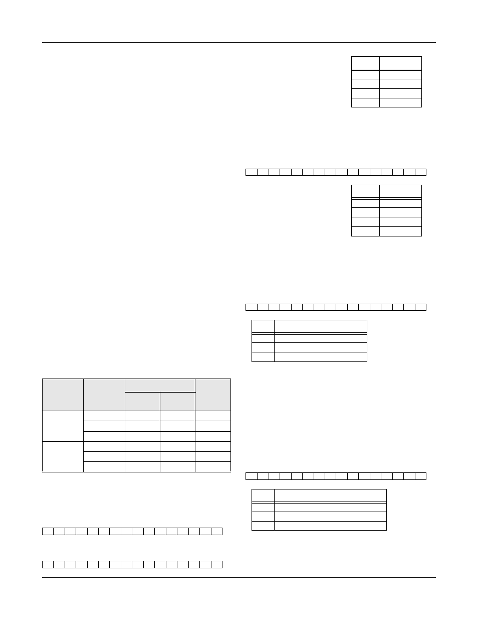
Monitoring Captured Events
All three counter Capture flags may be simultaneously read
from the status port:
When set, each of these three status bits indicate that the
corresponding channel captured an event. The captured
event type is either index or rollover.
If a counter channel has been programmed to capture both
index and rollover events, it may be necessary to determine
whether a captured event was an index or a rollover. All
three counter IndexCapture flags may be simultaneously
read from the extended status port:
When set, each of these three status bits indicate that the
corresponding channel captured an index event.
Operating
Mode
CM<1:0>
Captured Events
Reset
on
Index
Index
Rollover
Counter
00
•
•
01
•
10
•
•
Timer
00
•
•
•
01
•
10
•
•
Counter Control Port (base + 16, write only) : CM1 Bit
15
14
13
12
11
10
9
8
7
6
5
4
3
2
1
0
V
0
0
1
0
0
0
0
0
0
A1
A0
0
0
0
0
Counter Control Port (base + 16, write only) : CM0 Bit
15
14
13
12
11
10
9
8
7
6
5
4
3
2
1
0
V
0
0
0
1
0
0
0
0
0
A1
A0
0
0
0
0
V=1 to set CMx bit to 1,
V=0 to reset CMx bit to 0.
A
1
and A
0
specify which counter
channel is to be addressed:
A
1
A
0
Encoder
00
Channel 0
01
Channel 1
10
Channel 2
11
Not Valid
Counter Control Port (base + 16, write only) : Arm/Disarm
15
14
13
12
11
10
9
8
7
6
5
4
3
2
1
0
V
0
0
0
0
1
0
0
0
0
A1
A0
0
0
0
0
V=1 to arm event capture,
V=0 to disarm event capture.
A
1
and A
0
specify which counter
channel is to be armed/disarmed:
A
1
A
0
Encoder
00
Channel 0
01
Channel 1
10
Channel 2
11
Not Valid
Status Port (base + 22, read only) : Capture Flags
15
14
13
12
11
10
9
8
7
6
5
4
3
2
1
0
x
CP2 CP1 CP0
x
x
x
x
x
x
x
x
x
x
x
x
Bit
Function
CP2
Counter Channel 2 Capture Flag
CP1
Counter Channel 1 Capture Flag
CP0
Counter Channel 0 Capture Flag
StatusX Port (base + 54, read only) : IndexCapture Flags
15
14
13
12
11
10
9
8
7
6
5
4
3
2
1
0
x
CX2 CX1 CX0
x
x
x
x
x
x
x
x
x
x
x
x
Bit
Function
CX2
Counter Channel 2 IndexCapture Flag
CX1
Counter Channel 1 IndexCapture Flag
CX0
Counter Channel 0 IndexCapture Flag