Programmable counters – Sensoray 526 User Manual
Page 7
7
Programmable Counters
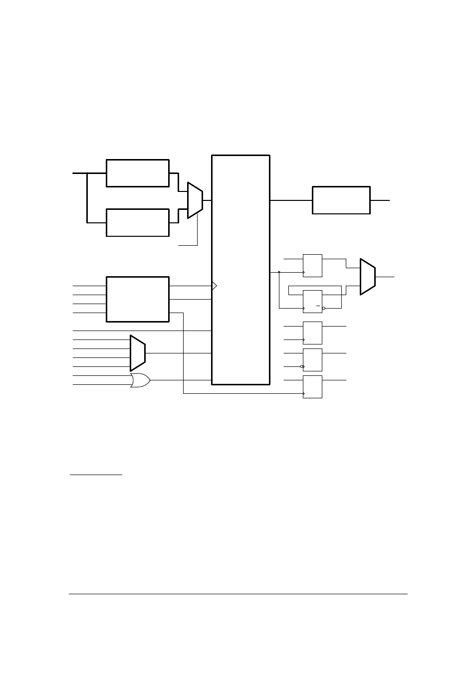
Model 526 contains 4 identical 24-bit up/down counters with enable and preload. The block
diagram of one of the counters is shown on Fig.2.
"1"
ECAP
SOFTWARE LOAD
PRELOAD BUFFER 0
UP/DOWN
POWER-ON RESET
CLKB
INTERNAL
INDEX
INDEX
.
.
.
"1"
CLK
D
Q
DATA BUS
CLKA
SOFTWARE RESET
RTGL
"1"
ICAP-
ENABLE
CLK
D
Q
CLK
D
Q
Q
COUNTER CORE
LOAD
ROLLOVER
LATCH
RTGL
INDEX^
ROLLOVER
CE
CLOCK
RCAP
CLK
D
Q
INDEXv
COUT
CLOCK MUX/
QUADRATURE
DETECTOR
PRELOAD BUFFER 1
RESET
INTERNAL/2
CLK
D
Q
"1"
ICAP+
ERROR
DATA BUS
Fig.2. Counter simplified block diagram.
See the description of Counter Mode register and Counter Control/Status register in the
Registers section for the implementation specifics.
Input Signals
The counter accepts the following input signals (connector J5):
•
CLKA – phase A of the encoder, or any clock signal in normal mode;
•
CLKB – phase B of the encoder;
•
INDEX – index signal of the encoder, or any digital signal;
•
CE – external count enable.
Signals CLKA, CLKB and INDEX could be either differential (RS-422), or single-ended. In case of a
single-ended signal the “+” input has to be used.
The clock source can be selected through the software. In quadrature mode the possible clock
sources are:
•
quadrature x1 (CLKA
↑
counting up, CLKA
↓
counting down);