Driver back panel, Dial switch, Hardware orientation – RGBLink Driver User Manual User Manual
Page 23
2. Hardware Orientation
Driver Back Panel
Driver User Manual 23
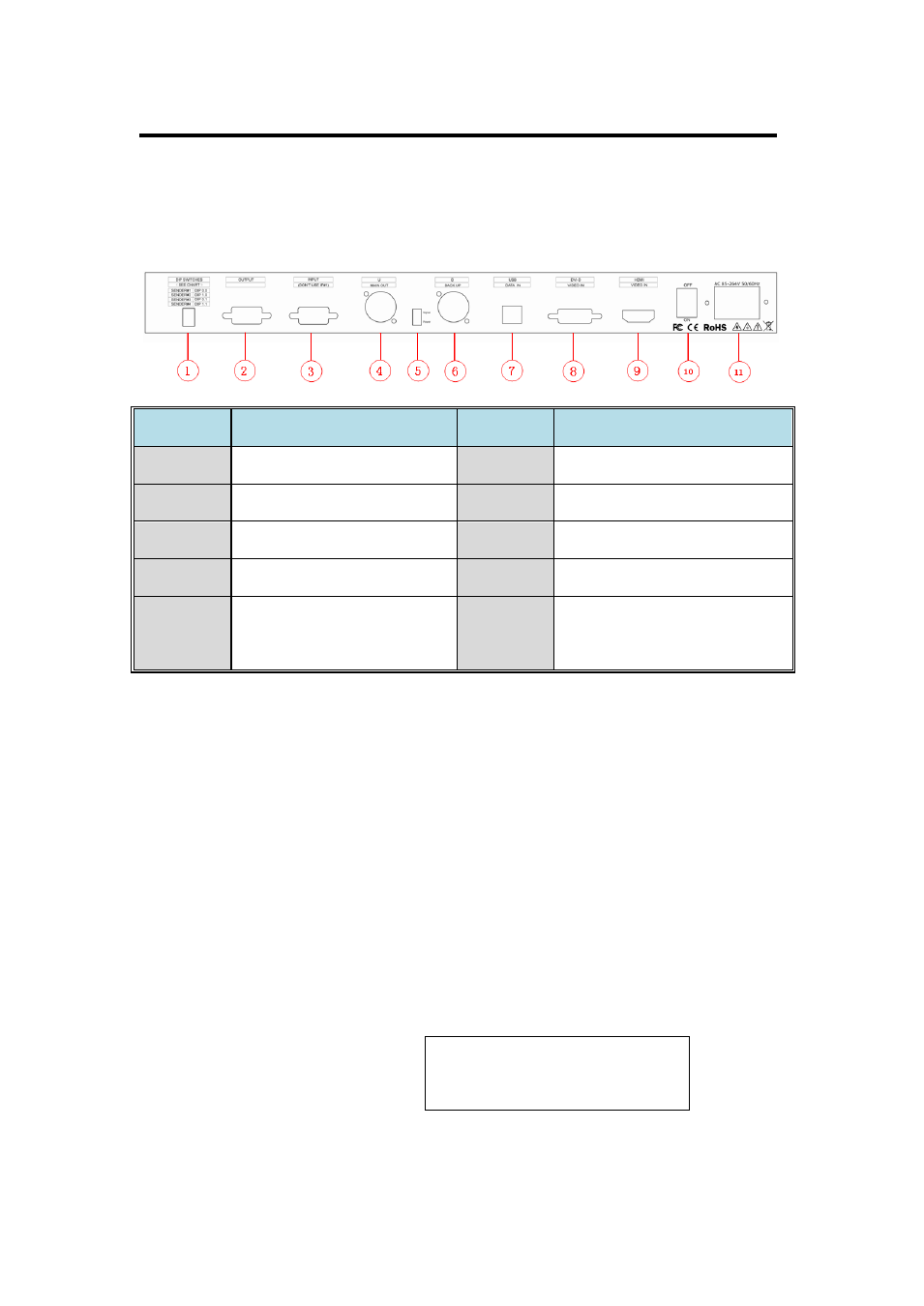
The figure below illustrates the professional interface and control signals
of Driver back panel:
1: Dial Switch
Dial switch 1 and dial switch 2 upward: Operation for the first controller.
Dial switch 1 downward and dial switch 2 upward: Operation for the
second controller.
Dial switch 1 upward and dial switch 2 downward: Operation for the
third controller.
Dial switch 1 and dial switch 2 downward: Operation for the fourth
controller.
Note
Dial switch operation only when
cascade, and cascade is only
available for Linsn sending card.
NO
INTERFACE
NO
INTERFACE
1
Dial switch
8
DVI Input
2. 3
RS232 control port
9
HDMI Input
4. 6
Gigabit Copper Port
10
Switch
5
LED Indicator
11
Power
7
USB control port of sending
card