3 wires in a shielded cable. the polarotor – Research Concepts RC2000A User Manual
Page 22
22
RC2000A Dual Axis Antenna Controller
Chapter 3
Installation
Research Concepts, Inc. can supply cable for installation. RCI part number CBL-2_16-3_22A contains
2 16 gauge conductors for carrying the motor drive current and a shielded triple with a drain wire in a
single UV resistant-direct burial jacket. Contact RCI for details.
Polarotor
TM
- 3 wires in a shielded cable.
The Polarotor
TM
is commonly supplied with a 3-wire interface using red, white, and black wires. If no
other documentation exists from the device manufacturer, the red wire should be connected to 5.7V (J1
pin 11), the white wire to pulse (J1 pin 10) and the black wire to return (J1 pin 9).
NOTE: A SHIELDED CABLE IS REQUIRED FOR THE POLAROTORTM TO MINIMIZE NOISE
PICKUP. THE SHIELD MUST BE CONNECTED TO J1-9 ON THE BACK OF THE CONTROLLER
AND MUST NOT BE CONNECTED AT THE ANTENNA.
Azimuth and Elevation Position Sense
If reed switch sensors are used, each axis requires 2 wires in a shielded cable. If Hall effect sensors
are used, each axis requires 3 wires in a shielded cable. Shielded cables are required to minimize noise
pickup which can result in antenna positioning errors. Please refer to figure 3.2 for reed sensor
connections and figure 3.3 for Hall Effect sensor connections.
NOTE: SHIELDED CABLES ARE REQUIRED FOR THE POSITION SENSORS. THE SHIELDS BE
MUST CONNECTED TO PINS J1-4 OR J1-6 ON THE BACK OF THE CONTROLLER AND MUST NOT
BE CONNECTED AT THE ANTENNA.
Position count errors due to improper use of the shield on the position sense lines is one of the most
frequent problems encountered during the installation of the RC2000A. Here are the problems that are
encountered.
1. A shielded cable was not used for the position sense wires.
2. The shield is not connected at the connector on the rear panel of the RC2000A.
3. The shield is connected to earth ground at the antenna. This results in ground currents flowing in
the shield. The shield must not be connected to anything at the antenna.
4. The insulator on the sensor cable is broken and the shield is grounded to something. As in #3, this
results in ground currents.
5. The sensor cable is spliced but the shield has not been spliced or the shield is spliced but is also
shorted to earth ground.
J3
1
AGC POTS
COMM
J1
O
F
F
S
E
T
N
I
A
G
AGC1
AGC2
1
7
.5
V
E
S
L
U
P
V
H
+
Z
A
+
L
E
E
L
-
A
Z
-
N
T
R
2
C
G
A
C
G
A
AZ DRIVE (2)
EL DRIVE (2)
SKEW
AUTOPOL INPUT
SENSORS
AGC INPUTS
G
N
D
G
N
D
1
Z
A
1
L
E
E
L
2
A
Z
2
1
J2
A
2
1
DRIVE
BREAKER
Research Concepts, Inc.
Lenexa, Kansas
Model: R C2000A
Serial Numb er: 226 1
Date : 02.02.98
EIC Input Power
J4
RTN
RE F
S IG
DRIV E
1 2 3 4 5
O
F
F
S
E
T
N
I
A
G
N
T
R
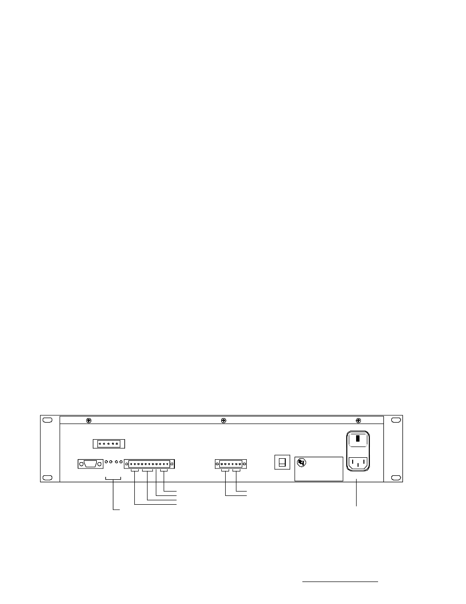
Figure 3.1 RC2000A Back Panel
Research Concepts, Inc. • 5420 Martindale Road • Shawnee, Kansas • 66218-9680 • USA www.researchconcepts.com