REMKO RVD 351 DC User Manual
Page 5
The equipment is shipped in sturdy
transport packaging. Immediately
check the equipment on delivery and
make a note of any damage or miss-
ing parts on the delivery note. Inform
the forwarding agent and contractual
partner. Warranty claims at a later
date will not be accepted.
The RVD 351-521DC room air
conditioning units have a REMKO
RVD...AT outdoor component as
well as an indoor unit RVD...IT.
The outdoor unit serves to output
the heat extracted by the indoor
unit from the room being cooled.
In heating operation, the heat
absorbed by the outdoor compo-
nent can be discharged through
the indoor unit into the room being
heated.SFlbIn both operating modes,
the performance of the compressor
precisely adjusts itself to the de-
mand, thereby regulating the target
temperature with minimal tempera-
ture variations. This "inverter-tech-
nology" enables power saving over
conventional split systems and also
reduces noise emissions to a particu-
larly low level.
The outdoor component is mounted
outdoors or under the observa-
tion of certain requirements it may
be installed indoors. The outdoor
component consists of a refrigerant
circuit with compressor, fin liquefier,
liquefier fan, reverse flow valve and
flow regulator. The outdoor unit is
controlled via the regulation of the
indoor unit.
The indoor unit is designed for
indoor installation in suspended
ceilings with Euroraster dimensions.
The cassette is hidden behind the
suspended ceiling, only its cover is
visible. Operation is undertaken via
an infrared remote control unit. The
indoor unit consists of a fin vapor-
iser, vaporiser fan, regulation system
and condensation pan.
Floor consoles, wall consoles, re-
frigerant pipes and a winter control
program are available as accessories.
Description of the
equipment
Transport and
Packaging
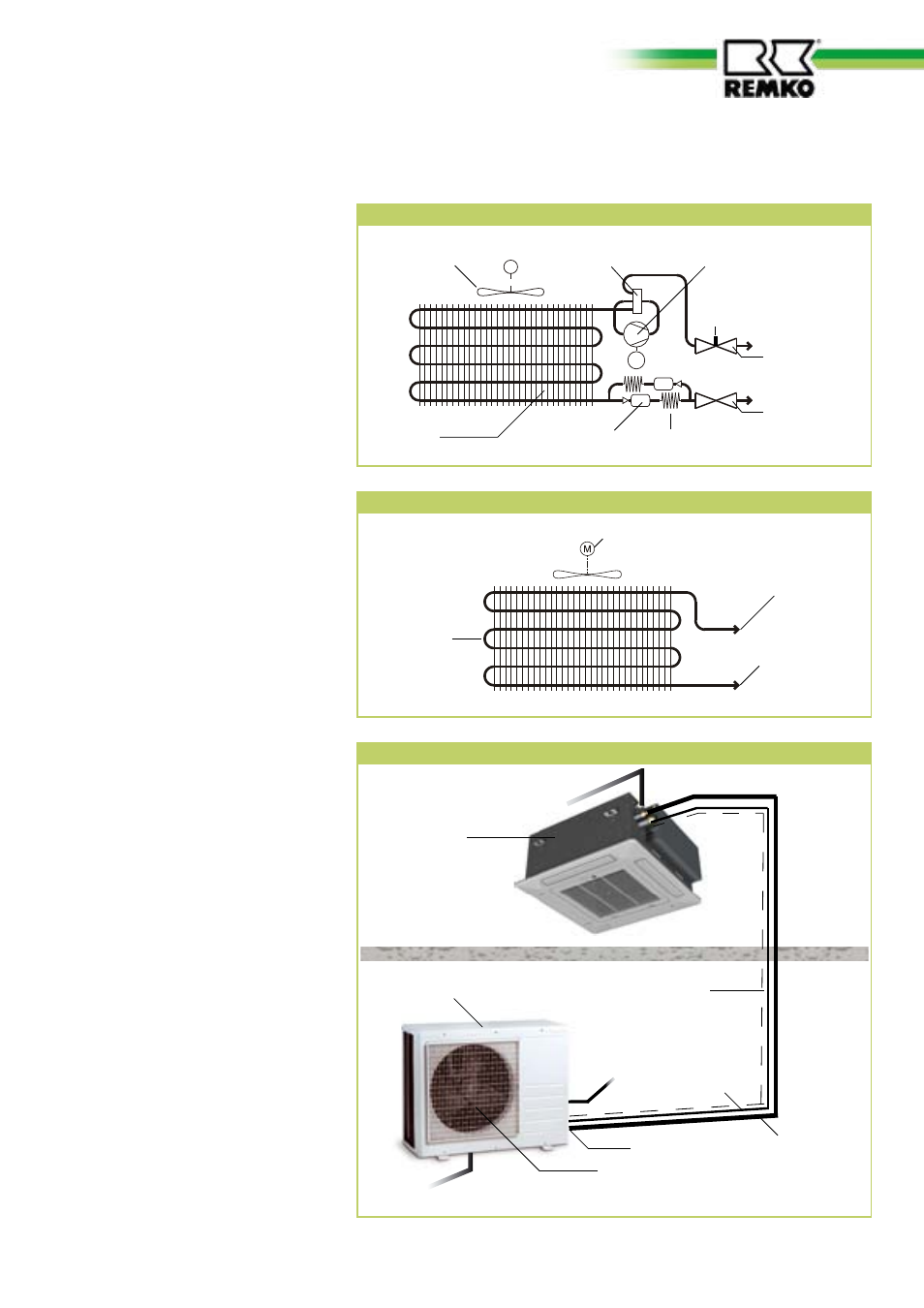
The connection between the indoor unit and the outdoor component is
made with refrigerant pipes.
Schematic of refrigerant circuit in indoor unit - cooling
Vaporiser fan
Connection to suction pipe
Connection to injection line
Vaporiser
Schematic of outdoor refrigerant circuit
M
M
Liquefier fan
Reverse flow valve
Liquefier
Filter dryer
Restrictor element exp. or capillary tube
Connection
valve
Injection pipe
Connection
valve
Suction pipe
Compressor
Connection
Manometer
Exterior unit
System layout
Stop valve
Interior unit
Liquefier fan
Outdoor area
Injection pipe
Suction pipe
Control line
Indoor area
Condensation line
Mains cable
Condensation line
5