Remko rvd...dc, Installation instructions for qualified personnel – REMKO RVD 351 DC User Manual
Page 16
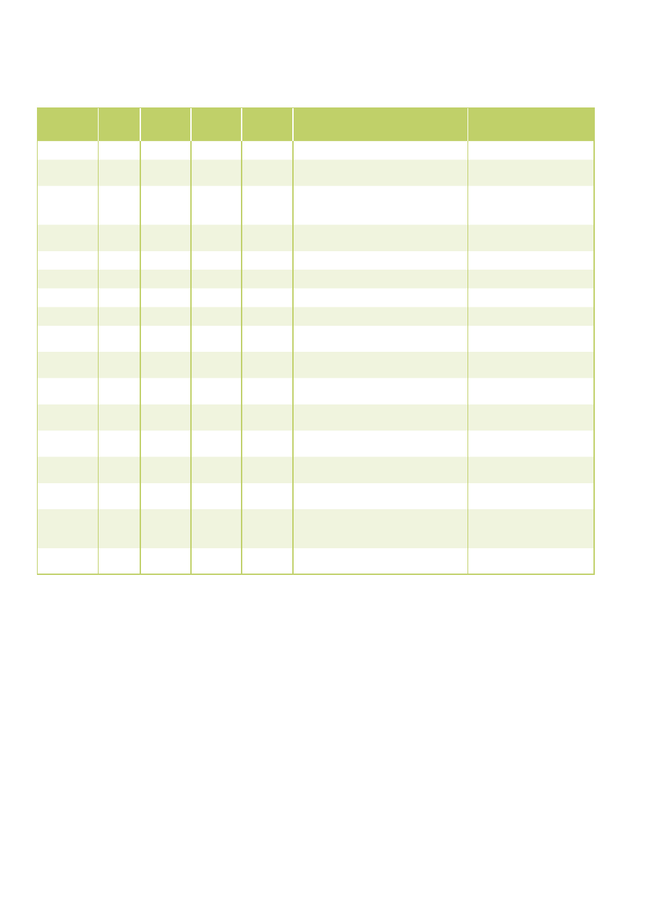
Problem display by blinker code
Installation instructions for qualified personnel
Important points prior to in-
stallation
■
Transport the unit in its original
packaging as close as possible
to the installation location to
avoid transport damage.
■
Check the contents of the
packaging for completeness
and check the unit for visible
transport damage. Report any
damage immediately to your
contracting party and the ship-
ping company.
■
Lift the unit at the corners and
not by the refrigerant or con-
densation connections.
■
The refrigerant pipes
(injection and suction pipe),
valves and connections must be
insulated impervious to vapour
diffusion. If necessary, also insu-
late the condensation pipe.
■
Select an installation location
which allows air to freely flow
through the inlet and outlet.
(See section "Minimum clear-
ances").
■
Do not install the unit in the
immediate vicinity of devices
with intensive thermal radia-
tion. Installation near sources of
thermal radiation reduces the
output of the unit.
■
Open the blocking valves of the
refrigerant pipes only after the
installation is complete.
■
Seal off open refrigerant pipes
with suitable caps or adhesive
strips to avoid infiltration of
moisture
and never kink or compress the
refrigerant pipes.
■
Avoid unnecessary
bends. This minimises the pres-
sure loss in the refrigerant pipes
and ensures that the compres-
sor oil can flow back without
obstruction.
LED
Operation
LED
Timer
LED
Defrost
LED
Alarm
Display
outdoor
unit
Cause
Required action
E0
EEPROM error
Check EEPROM
E2
Communication error between PCBs
outdoor unit & indoor unit
Check electrical connection
leads
E3
Communication error between out-
door unit main board & outdoor unit
inverter board
Check wiring
E4
Outdoor temp sensor on outdoor com-
ponent tripped
Check resistance and tem-
perature on sensor
E5
Overvoltage compressor
Check compressor voltage
P0
Excessive temperature compressor
Allow compressor to cool
P1
High pressure sensor has triggered
Check refrigerant pressure
P2
Low pressure sensor has responded
Check refrigerant pressure
P3
Compressor power consumption too
high
Check compressor power
consumption
P4
Compressor discharge gas over 105°C
Clean liquefier, check refrig-
erant circuit
P5
Liquefier temperature over 65°C
Clean liquefier, check refrig-
erant circuit
P6
Voltage protection main board outdoor
unit
Check voltage
flashes
rapidly
Sensor air circulation / sensor liquefier
tripped
Check resistance
flashes
rapidly
Communication error between outdoor
unit & indoor unit
Check electrical connection
leads
flashes
rapidly
Mode malfunction
Switch system off
flashes
slowly
flashes
slowly
flashes
slowly
flashes
slowly
Sensor liquefier / outdoor temp faulty
or not correctly connected
Read off error code on
outdoor unit
Check sensors
flashes
rapidly
Condensate pump float switch faulty
Check condensate pump
and float switch
REMKO RVD...DC
16