Remko rvd...dc – REMKO RVD 351 DC User Manual
Page 24
Functional test and
test run for RVD 521 DC
During operation of the plant
operating parameters can be called
up on the outdoor unit display.
The following parameters are dis-
played successively:
RVD 521 DC
- Frequency of the compressor
- Operating mode
- Level fan
- Current cooling/heating perforance
- Temperature sensor liquefier
- Temperature sensor hot gas
- Temperature sensor air inlet
- Power consumption outdoor unit
- Degree of opening for electronic
Expansion valve only RVD 521 DC
- error code
Proceed as follows to call up the
operating parameters:
1. Remove the cover from the
outdoor unit.
2. Switch all indoor units on and
select cooling mode and the
highest fan speed.
Frequency gauge
Temperature sensor air inlet
Temperature sensor liquefier
Operating mode
Operating mode fan
Cooling - heating output AT / IT
Display
Frequency (Hz)
30
30
--
Stand by
60
60
Display
Mode AT
0
Off
2
Cooling mode
3
Heating mode
4
Forced cooling
Display
Mode fan
0
Off
1
Low rotational speed
2
High rotational speed
Display
Cooling output
1
2.0-2.5 kW
2
2.5-3.0 kW
3
3.0-3.8 kW
4
3.8-5.0 kW
5
5.0-5.5 kW
6
5.5-6.1 kW
Display
Temperature
10
35-40 ℃
11
40-45 °C
12
45-50 ℃
13
50-55 °C
14
55-60 ℃
15
60-65 °C
16
65-70 ℃
Display
Temperature
15
-7.5 ℃
20
-5.0°C
25
-2.5℃
30
0°C
35
2.5℃
40
5.0°C
45
7.5℃
50
10.0°C
55
12.5℃
60
15.0°C
65
17.5°C
70
20.0°C
75
22.5°C
80
25.0°C
85
27.5°C
90
30.0°C
95
32.5°C
99
34.5°C
Power consumption outdoor unit
Display
Power consump-
tion
44
6.0 A
46
6.2 A
54
7.4 A
55
7.6 A
58
7.8 A
62
8.0 A
66
8.6 A
67
8.8 A
68
9.0 A
70
9.2 A
72
9.5 A
76
10.0 A
78
10.2 A
80
10.4 A
82
10.6 A
84
11.0 A
88
11.6 A
92
12.0 A
94
12.2 A
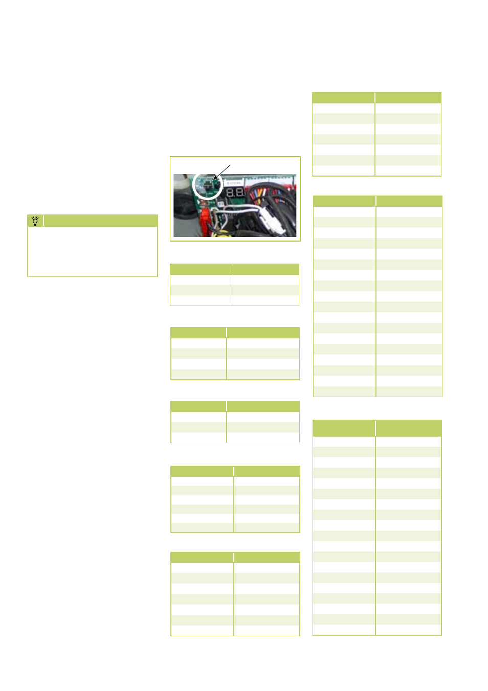
Check button
Display RVD 521 DC
The display on the outdoor unit
PCB can call up the operating pa-
rameters of the plant in the above
order. In order to do so, press the
check button located next to the
display on the AT board.
Temperature sensor hot gas
Display
Temperature
10
35-40 ℃
11
40-45 °C
12
45-50 ℃
13
50-55 °C
14
55-60 ℃
15
60-65 °C
16
65-70 ℃
1. Check all the previously
described safety devices and
functions during the test run.
12. Enter the measured data in
the commissioning report.
in the commissioning report
and familiarize the operator
with the system.
13. Remove the pressure gauge.
Check that seals have been
fitted in the sealing caps.
14. Reinstall all parts which were
removed.
NOTE
Press the TEST knob on the
outdoor unit board. This
serves to set the inverter to
max. refrigerating capacity.
REMKO RVD...DC
24