Quantum Composers AF910 User Manual
Page 38
Page 38
AF910 Manual Version 1.4
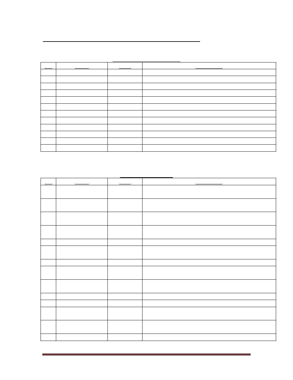
Adapter Board # 300001-026 Connections (Opto-Isolated)
Connector Types: Hirose DF11 Series, # DF11-12DS-2C.
Sockets: # DF11-2428SC (24-28 AWG).
Power and Communication
Pin
Name
Type
Description
1
GND
Power
Ground
2
N/C
N/A
No connection
3
+12VDC
Power
Positive supply voltage (350mA)
4
+12VDC
Power
Positive supply voltage (350mA)
5
GND
Power
Ground
6
GND
Power
Ground
7
Rx IN
Input
RS232 receive
8
Tx OUT
Output
RS232 transmit
9
N/C
N/A
No connection
10
GND
Power
Ground
11
N/C
N/A
No connection
12
N/C
N/A
No connection
Connector Types: Hirose DF11 Series, # DF11-14DS-2C.
Sockets: # DF11-2428SC (24-28 AWG).
Opto-Isolated Signals
Pin
Name
Type
Description
1
ANALOG OUT
Output
+/-10V analog output corresponding to focus position.
Zero volts indicates in focus. Not opto-isolated.
2
/IN RANGE
Output
Open collector output. Active low when signal is in
range
3
/IN FOCUS
Output
Open collector output. Active low when signal is in
focus
4
AF STATUS
Output
TTL active high output. High level indicates autofocus
is enabled
5
GND
Power
Ground
6
EMO
Input
TTL active high input. Stops autofocus and motor
movement
7
/LASER DISABLE Input
Active low input to disable laser diode
8
LIMIT A
Input
TTL active low input. Positive direction limit switch
input (A)
9
LIMIT B
Input
TTL active low input. Negative direction limit switch
input (B)
10
RESERVED
N/A
Reserved – Do not connect
11
GND
Power
Ground
12
STEP
Output
Buffered TTL signal output for motor step. Not opto-
isolated.
13
DIRECTION
Output
Buffered TTL signal output for motor direction. Not
opto-isolated.
14
+24V External
Opto Power
+24V from external source to power opto-isolators.