Motor controller description and setup, Otor, Ontroller – Quantum Composers AF910 User Manual
Page 18: Escription and, Etup
Page 18
AF910 Manual Version 1.4
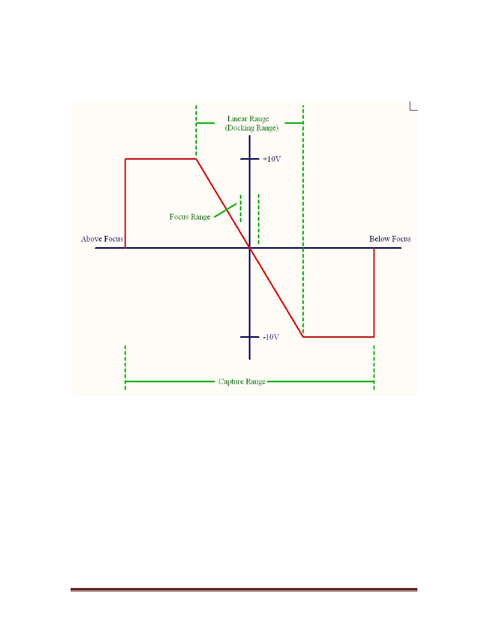
docking range, which is also outside of the linear range. The sign of the signal can be
used as a method to determine the direction of focus. There is a method to scale the
output when inside of the linear range. This is the analog scalar (AS) command described
in the command set section.
Figure 14 Analog Output
Motor Controller Description and Setup
The AF91x includes built in motor control functions that can directly drive most motor
driver modules that accept motor step and direction signals. This eliminates the need for a
separate motor controller module to process the analog output signal and convert to a step
and direction. The motor control functions consist of the following features:
-
Motor step signal.
-
Motor direction signal.
-
Two limit switch inputs.
-
Homing function.
-
32 bit position counter (± 2,147,483,647 counts).
-
Configurable limit switch polarities.
-
Configurable motor directions.