Quantum Composers AF910 User Manual
Page 36
Page 36
AF910 Manual Version 1.4
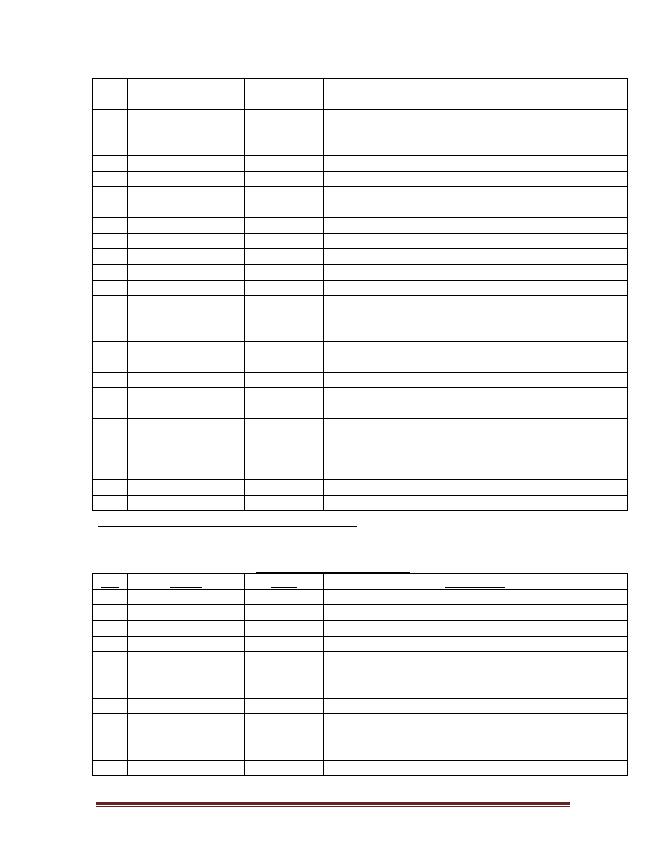
10
LIMIT B
Input
TTL active low input. Negative direction limit switch
input (B)
11
LIMIT A
Input
TTL active low input. Positive direction limit switch
input (A)
12
RESERVED
N/A
Reserved – Do not connect
13
RESERVED
N/A
Reserved – Do not connect
14
Rx IN
Input
RS232 receive
15
Tx OUT
Output
RS232 transmit
16
GND
Power
Ground
17
RESERVED
N/A
Reserved – Do not connect
18
RESERVED
N/A
Reserved – Do not connect
19
RESERVED
N/A
Reserved – Do not connect
20
+5VDC
Output
Reference output. 50mA max.
21
/LASER DISABLE Input
Active low input to disable laser diode
22
RESERVED
N/A
Reserved – Do not connect
23
AF STATUS
Output
TTL active high output. High level indicates autofocus
is enabled
24
EMO
Input
TTL active high input. Stops autofocus and motor
movement
25
GND
Power
Ground
26
/IN RANGE
Output
Open collector output. Active low when signal is in
range
27
/IN FOCUS
Output
Open collector output. Active low when signal is in
focus
28
ANALOG OUT
Output
+/-10V analog output corresponding to focus position.
Zero volts indicates in focus
29
STEP
Output
TTL signal output for motor step
30
DIRECTION
Output
TTL signal output for motor direction
Adapter Board # 300001-018 Connections
Connector Types: Hirose DF11 Series, # DF11-12DS-2C.
Sockets: # DF11-2428SC (24-28 AWG).
Power and Communication
Pin
Name
Type
Description
1
GND
Power
Ground
2
N/C
N/A
No connection
3
+12VDC
Power
Positive supply voltage (350mA)
4
+12VDC
Power
Positive supply voltage (350mA)
5
GND
Power
Ground
6
GND
Power
Ground
7
Rx IN
Input
RS232 receive
8
Tx OUT
Output
RS232 transmit
9
N/C
N/A
No connection
10
GND
Power
Ground
11
N/C
N/A
No connection
12
N/C
N/A
No connection