Vcm-x co, Vcm-x co appendix, Troubleshooting – Orion System System Manager TS II In-House User Manual
Page 70
Zone
Zone
VCM-X Co
VCM-X Co
Appendix
SMTS II Technical Guide
70
Troubleshooting
System Manager TS II LEDs, Buttons,
Dipswitches & Jumpers
LEDs and system function buttons are located behind your System
Manager TS II’s cover. See Figure 137 for locations. Dipswitches and
jumpers are located on the back of your System Manager TS.
Power LED
This LED will light up and stay on as long as power is supplied to
your TS.
Operation LED
This LED will blink once a second to indicate that the system is alive.
Update LED
This LED will turn on when the Update program is running.
Screen Refresh LED
This LED will turn on when the screen refreshes.
Communications LED
This LED will light up and blink when there is a connection with the
CommLink and/or network. If you are using your TS in stand-alone
mode, this LED will not light up.
Reset Button
Press this button to reset the screen. The screen should refresh itself to
the Main Screen within 2 minutes.
Diagnostics Button
Under the direction of WattMaster Controls Technical Support, you
may have to perform diagnostics on your System Manager TS II. Press
this button to do so.
Touch Screen Suspend Button
Press this button to temporarily freeze the touch screen function of your
System Manager TS II in order to clean the screen. Always use a dry,
dust -free cloth to clean the screen.
OPT1 Dipswitch
For High Speed applications, the OPT1 Dipswitch should be ON. For
all other applications, it should be OFF. This Dipswitch is located on
the back of the System Manager TS. See Figures 5-8, pages 8-11 for
location.
OPT4 Dipswitch
As of April 2014, Dipswitch OPT4 should be set to ON by default.
Previous versions should be set to OFF. If you see your screen is not
centered correctly, switch OPT4 to the opposite position. This Dipswitch
is located on the back of the System Manager TS. See Figures 5-8,
pages 8-11 for location.
TERM Jumpers
Both TERM Jumpers must be ON for Stand-Alone applications
(No CommLink or MiniLink). Both TERM Jumpers must be OFF for
applications with CommLink(s) and/or MiniLink(s). See Figures 5-8,
pages 8-11 for location.
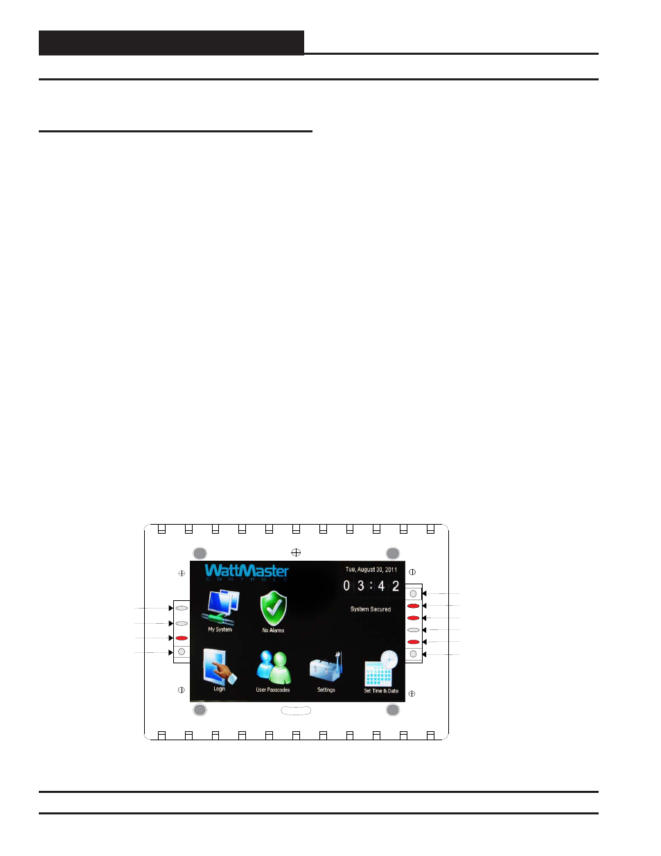
Reset Button
A302-12
Power LED
Communications LED
Diagnostics Button
Suspend Button
Not Used
Not Used
Screen Refresh LED
Operation LED
Update LED
Figure 137: System Manager TS II LEDs and Buttons
Revised 4/21/14