Controller installation & wiring, Hb mini controller technical guide 5, Controller mounting – Orion System HB Mini User Manual
Page 5: Important wiring considerations, Figure 2: hb mini controller wiring
HB Mini Controller
Technical Guide
5
Controller Installation & Wiring
Controller Mounting
It is important to mount the controller in a location that is free from
extreme high or low temperatures, moisture, dust and dirt. Be careful
not to damage the electronic components when mounting the control-
ler. The HB Mini Controller mounts in the HB unit control panel using
the 4 plastic standoffs located on the HB control enclosure mounting
base.
Important Wiring Considerations
Please carefully read and apply the following information when wiring
the HB Mini Controller.
1.
All 24 VAC wiring must be connected so that all ground
wires remain common. Failure to follow this procedure
can result in damage to the controller and connected
devices.
2.
All wiring is to be in accordance with local and national
electrical codes and specifications.
3.
Minimum wire size for 24 VAC thermostat wiring should
be 22 gauge.
4.
Minimum wire size for all sensors should be 24 gauge.
5.
Be sure that all wiring connections are properly inserted
and tightened into the terminal blocks. Do not allow wire
strands to stick out and touch adjoining terminals which
could potentially cause a short circuit.
6.
Be sure all modular wiring harness connectors are seated
firmly in their respective modular connectors on the HB
Mini circuit board.
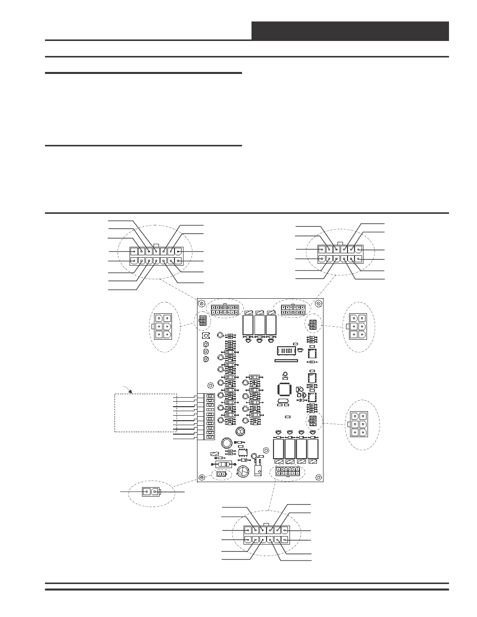
Figure 2: HB Mini Controller Wiring
ECONO SECTION
HEAT SECTION
HIGH SPEED
SERIAL
COMMUNICATIONS
CONNECTOR
PERIPHERAL BUS
CONNECTOR
HIGH SPEED
SERIAL
COMMUNICATIONS
CONNECTOR
HSS
P-BUS
HSS
P3
P11
P8
COOLING SECTION
P9
P4
P10
24V
AC
GND
P1
PIN2 - GND
PIN2 - 24 VAC
PIN2 - VFD
PIN3 - SPARE IN
PIN3 - 24 VAC
PIN3 - GND
PIN4 - 24 VAC
(R) FROM THERMOSTAT
(C) FROM THERMOSTAT
(G) FROM THERMOSTAT
(Y1) FROM THERMOSTAT
(Y2) FROM THERMOSTAT
(W1) FROM THERMOSTAT
(W2) FROM THERMOSTAT
(W3) FROM THERMOSTAT
(C1) CLOGGED FILTER SWITCH 24 VAC OUTPUT
(C2) CLOGGED FILTER SWITCH 24 VAC OUTPUT
PIN5 - OAT
PIN4 - GND
PIN4 - LL_TMP
PIN6 - GND
PIN5 - HEAT_1
PIN5 - GND
PIN7 - 24 VAC
PIN6 - COM_1
PIN6 - COND
PIN14 - GND
PIN12 - GND
PIN12 - FAN
PIN2 - 24 VAC
PIN1 - GND
PIN13 - CO2
PIN11 - COM_23
PIN11 - LO_SPD
PIN12 - RAB
PIN10 - COM_23
PIN10 - HPS
PIN11 - 24 VAC
PIN1 - SW_24VAC
PIN1 - HEAT_1
PIN1 - GND
PIN8 - CFS
PIN7 - HEAT_2
PIN7 - COOL_2
PIN9 - ECONO POS
PIN8 - HEAT_3
PIN8 - COOL_1
PIN10 - GND
PIN9 - HT_MON
PIN9 - LPS
See Thermostat
Wiring Diagrams
For Complete Wiring
Connection Details
P1
HSS
P8
SW1
LD1
LD2
LD3
R
C
G
(GND)
Y1
Y2
W1
W2
C1
W3
C2
TB3
P10
24V
AC
GND
D23
R67
V10
R66
L1
C27
C25
C19
C15
C12
C1
R34
R40
R27
R71
C3
ECONO SECTION
K2
R12
R10 D20
R1
R2
R3
D5
R24
R26
R28
D8
R35
R37
R38
D10
R43
C18
R45
R47
D12
R52
C22
R54
R55
D14
R59
C28
R62
R64
D15
C30
D22
C29
R68
R69
C33
C32
C14
MADE IN THE USA
REV 1
HB MINI
YS102032
Q8
D21
V1
D19
Q7
Q9
SERIAL #
R30
R32
R36
D9
R41
U4
R42
R44
D11
R49
C23
R51
R53
D13
R60
R63
R65
D16
Q4
K5
C31
V5
VR2
P4
V9
D4
Q5
X1
K4
P9
V3
HEAT SECTION
C37
U5
P6
RN1
C38
C13
C17
C40
C24
C41
Q2
D17
V7
COOLING SECTION
V8
D2
Q3
R4
VR1
C39
U1
C5
P3
HSS
R8
R11
R13
HSS
DR
V
C20
U6
R58
R61
C46
P-BUS
DR
V
R75
R72
R73
R74
P-BUS
P11
D3