E-bus controller to dual digital module wiring, Dual digital module technical guide 8 – Orion System Dual Digital Module User Manual
Page 8
Dual Digital Module
Technical Guide
8
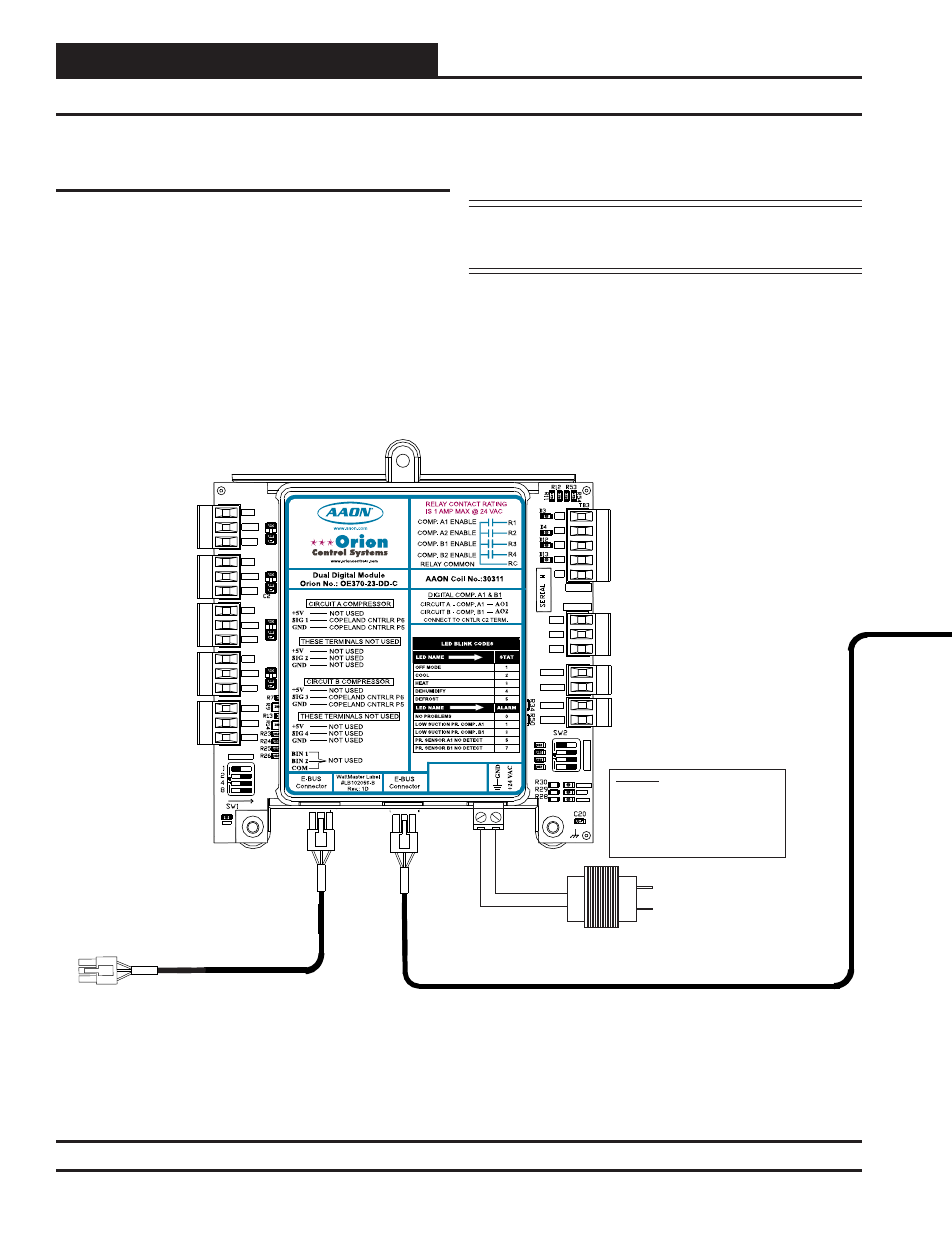
E-BUS Controller to Dual Digital Module Wiring
VCM-X Modular E-BUS Controller to
Dual Digital Module Wiring
The Dual Digital Module directly connects to the VCM-X Modular E-
BUS Controller using a modular HSSC cable. The Dual Digital Module
requires a 24 VAC power connection with an appropriate VA rating. See
Figure 5 below for wiring.
Any E-BUS Module can be connected to the E-BUS Controller’s E-BUS
port or can be daisy-chained together using HSSC cables.
NOTE: Contact Factory for the correct HSSC cable length for
your application. Cables are available in ¼, ½, 1, 2, 3,
4, and 5 Meter lengths and 100 and 150 Foot lengths.
Figure 5: VCM-X Modular E-BUS Controller to Dual Digital Module Wiring Diagram
Connect To Other
WattMaster-Approved
E-BUS Expansion Module(s)
HSSC Cable
HSSC Cable
Connect To VCM-X E-BUS Controller
OE370-23-DD-C
Dual Digital Module
+5V
SIG 2
GND
OPTI
O
N
S
ALARM
ANALOG
STAT
+5V
COMM
GND
SIG 4
GND
BIN 2
R1
R2
GND
RELAYS
ADDRESS
SIG 3
+5V
GND
BIN 1
COM
+5V
SIG 1
R3
R4
Rc
AO1
AO2
PWM1-
PWM1+
PWM2-
PWM2+
PWR
24 VAC Transformer
3 VA Minimum
Line Voltage
24 V
A
C
GND
WARNING!!
Observe Polarity! All boards must be wired with
GND-to-GND and 24 VAC-to-24 VAC. Failure to
observe polarity could result in damage to the
boards.