Installation and wiring – Orion System Dual Digital Module User Manual
Page 4
Dual Digital Module
Technical Guide
4
Environmental Requirements
The Dual Digital Module needs to be installed in an environment which
can maintain a temperature range between -30°F and 150°F and not
exceed 90% RH levels (Non-Condensing).
Mounting
The Dual Digital Module is housed in a plastic enclosure. It is designed
to be mounted by using the 3 mounting holes in the enclosure base. It is
important to mount the module in a location that is free from extreme high
or low temperatures, moisture, dust, and dirt. Be careful not to damage
the electronic components when mounting the module.
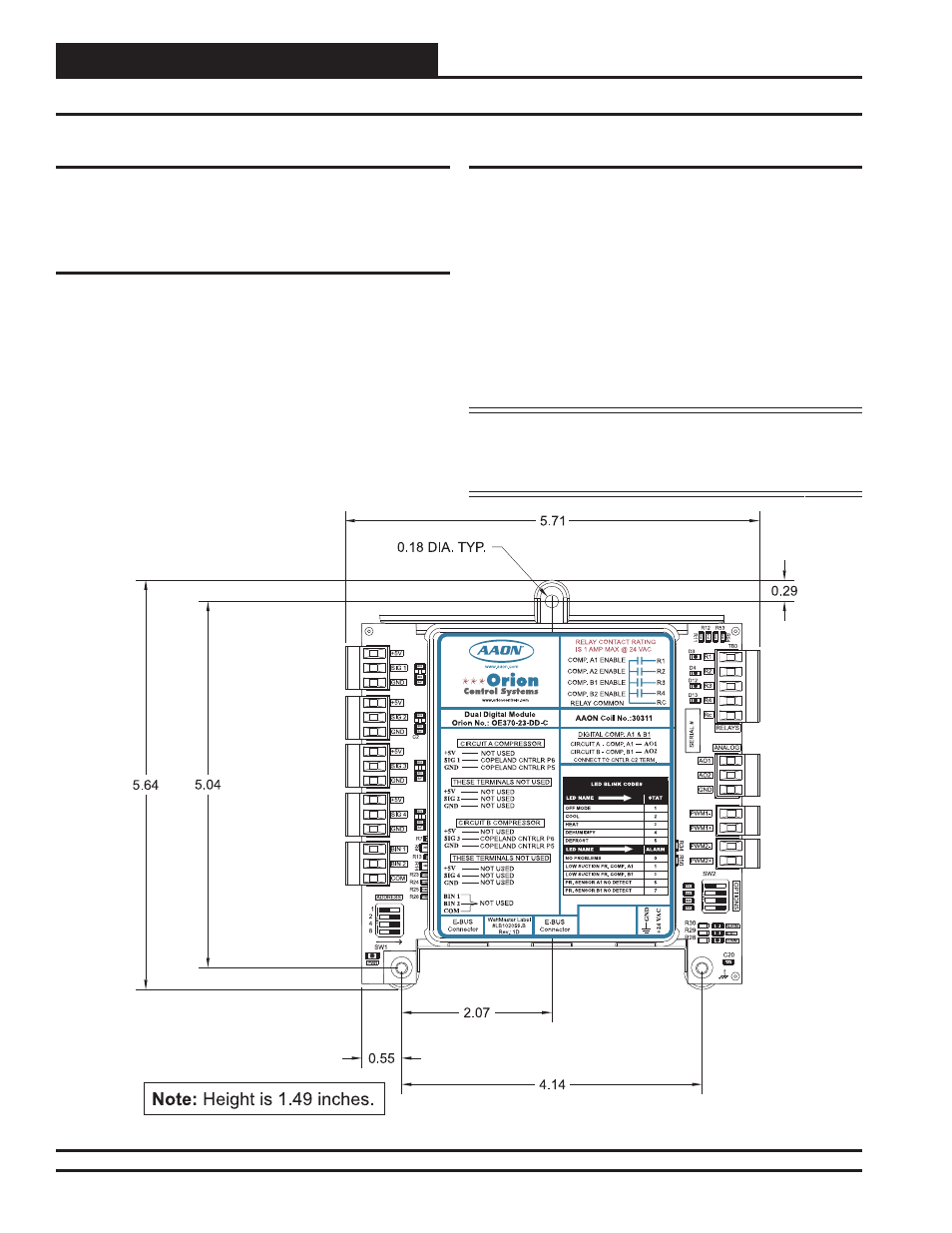
See Figure 2 for Module dimensions (dimensions are in inches).
Power Supply and Communications
The Dual Digital Module is connected to the E-BUS Distribution
Module with a modular HSSC cable to provide communications from
the VCM-X Modular Controller. The E-BUS Distribution Module uses
WattMaster Control’s standard I
2
C modular cable to connect with the
VCM-X Modular Controller, VCM-X Expansion Module, or 12-Relay
Expansion Module.
The Dual Digital Module can also be directly connected to the VCM-X
Modular E-BUS Controller, bypassing the use of the E-BUS Distribu-
tion Module.
The Dual Digital Module requires a 24 VAC power connection with an
appropriate VA rating.
WARNING: Observe polarity! All boards must be wired
GND-to-GND and 24 VAC-to-VAC. Failure to
observe polarity could result in damage to the
boards.
Installation and Wiring
Figure 2: Dual Digital Module Dimensions