Installation and wiring, Technical guide dual digital module 5, Important wiring considerations – Orion System Dual Digital Module User Manual
Page 5: Figure 3: dual digital e-bus connection wiring
Technical Guide
Dual Digital Module
5
Installation and Wiring
Important Wiring Considerations
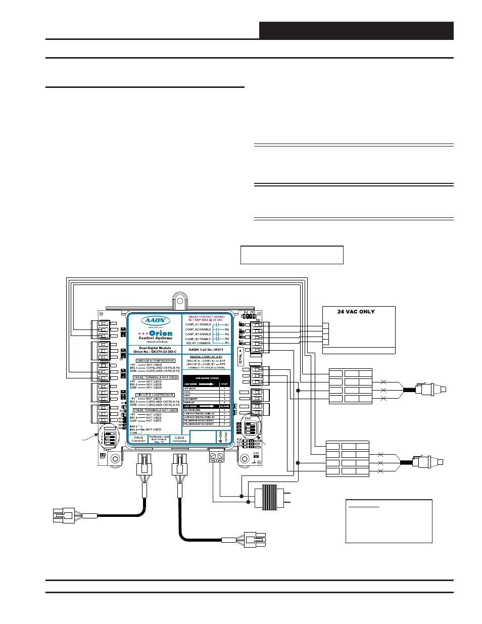
Please carefully read and apply the following information when wiring
the Dual Digital Module:
1. The 1 to 5 VDC signals for the Copeland Compressor
Speed need to use 18-gauge shielded twisted pair cable, and
the Drain wire must be the GND signal.
2. All 24 VAC wiring must be connected so that all ground
wires remain common. Failure to follow this procedure can
result in damage to the module and connected devices.
3. All wiring is to be in accordance with local and
national electrical codes and specifi cations.
4. Be sure that all wiring connections are properly inserted
and tightened into the terminal blocks. Do not allow wire
strands to stick out and touch adjoining terminals. This
could potentially cause a short circuit.
5. Be sure all modular wiring harness connectors are seated
fi rmly in their respective modular connectors on the circuit
board.
NOTE: The Compressor Relays on the Dual Digital Module
are used rather than the relay outputs on the VCM-X
Modular series controller.
WARNING: Be sure all controllers and modules are
powered down before connecting or
disconnecting HSSC cables.
Figure 3: Dual Digital E-BUS Connection Wiring
SHLD
OUT
COM
EXC
P4
BK
RD
WH
P2
P1
P3
P5
C1
C2
P6
SHLD
OUT
COM
EXC
P4
BK
RD
WH
P2
P1
P3
P5
A 1
O
SIG 1
SIG 3
GND
GND
GND
C1
C2
P6
+5V
SIG 2
GND
OPTI
O
N
S
ALARM
ANALOG
STAT
+5V
COMM
GND
SIG 4
GND
BIN 2
R1
R2
GND
RELAYS
ADDRESS
SIG 3
+5V
GND
BIN 1
COM
+5V
SIG 1
R3
R4
Rc
AO1
AO2
PWM1-
PWM1+
PWM2-
PWM2+
OE275-01 Suction
Pressure Transducer
OE275-01 Suction
Pressure Transducer
Connect To
E-BUS Distribution Module or
VCM-X Modular E-BUS Controller
OE370-23-DD-C
Dual Digital Module
Copeland Digital
Compressor Controller A1
Copeland Digital
Compressor Controller B1
This Dip
Switch Is Not
Used For This
Application
This Dip
Switch Is
Not Used
For This
Application
OE370-23-FD FULL DIGITAL COMPRESSOR MODULE
www.orioncontrols.com
+5V
SIG 2
GND
+5V
SIG 1
GND
+5V
SIG 3
GND
+5V
SIG 4
GND
BIN 1
BIN 2
COM
AO1
AO2
GND
NOT USED
NOT USED
NOT USED
NOT USED
COMPRESSOR #2
COMPRESSOR #1
COPELAND CNTRLR P6
COPELAND CNTRLR P6
COPELAND CNTRLR P5
COPELAND CNTRLR P5
NOT USED
RELAY CONTACT RATING
IS 1 AMP MAX @ 24 VAC
COMP. #2 ENABLE
COMP. #1 ENABLE
COMP. #1 CNTRLR C2
COMP. #2 CNTRLR C2
COMP. #1 & #2 CNTRLR C1
R1
R2
R3
R4
RC
NOT USED
NOT USED
RELAY COMMON
E-BUS
Connector
E-BUS
Connector
WattMaster Label
#LB102056
+2
4
VA
C
GN
D
PWR
A 2
O
NOTE:
NORMALLY
OPEN AND RATED FOR 24 VAC POWER ONLY
ALL RELAY OUTPUTS ARE
COMPRESSOR A2 ENABLE
COMPRESSOR A1 ENABLE
R1
R4
R3
R2
COMPRESSOR B1 ENABLE
COMPRESSOR B2 ENABLE
- 1 AMP MAXIMUM LOAD
HVAC UNIT CONNECTIONS
HSSC Cable
HSSC Cable
24 VAC Transformer
3 VA Minimum
Line Voltage
24 V
A
C
GND
WARNING!!
Observe Polarity! All boards
must be wired with GND-to-GND
and 24 VAC-to-24 VAC. Failure
to observe polarity could result in
damage to the boards.
Connect To Other
WattMaster-Approved
E-BUS Expansion Module(s)
COMM