Installation and wiring, Technical guide dual digital module 7, Modular cable connect to vcm-x modular controller – Orion System Dual Digital Module User Manual
Page 7
Technical Guide
Dual Digital Module
7
WARNING!!
Observe Polarity! All
boards must be wired with
GND-to-GND and 24 VAC-
to-24 VAC. Failure to
observe polarity could
result in damage to the
boards.
OE365-23-EBD E-BUS
Distribution Module
GND
-COMM
SHLD
+COMM
INPUT
+COMM
SHLD
-COMM
GND
+VDC
485 DRV
24VAC
GND
PWR
YS102308
REV 1
I2C TO COMM
DIST. BOARD
OUTPUT
Modular Cable
Connect To
VCM-X Modular Controller
HSSC Cable
Connect To E-BUS
Distribution Module
OE370-23-DD-C
Dual Digital Module
+5V
SIG 2
GND
OPTI
O
N
S
ALARM
ANALOG
STAT
+5V
COMM
GND
SIG 4
GND
BIN 2
R1
R2
GND
RELAYS
ADDRESS
SIG 3
+5V
GND
BIN 1
COM
+5V
SIG 1
R3
R4
Rc
AO1
AO2
PWM1-
PWM1+
PWM2-
PWM2+
PWR
Connect To Other
WattMaster-Approved
E-BUS Expansion Module(s)
HSSC Cable
24 VAC Transformer
3 VA Minimum
Line Voltage
24 V
A
C
GND
WARNING!!
Observe Polarity! All boards must be
wired with GND-to-GND and 24
VAC-to-24 VAC. Failure to observe
polarity could result in damage to the
boards.
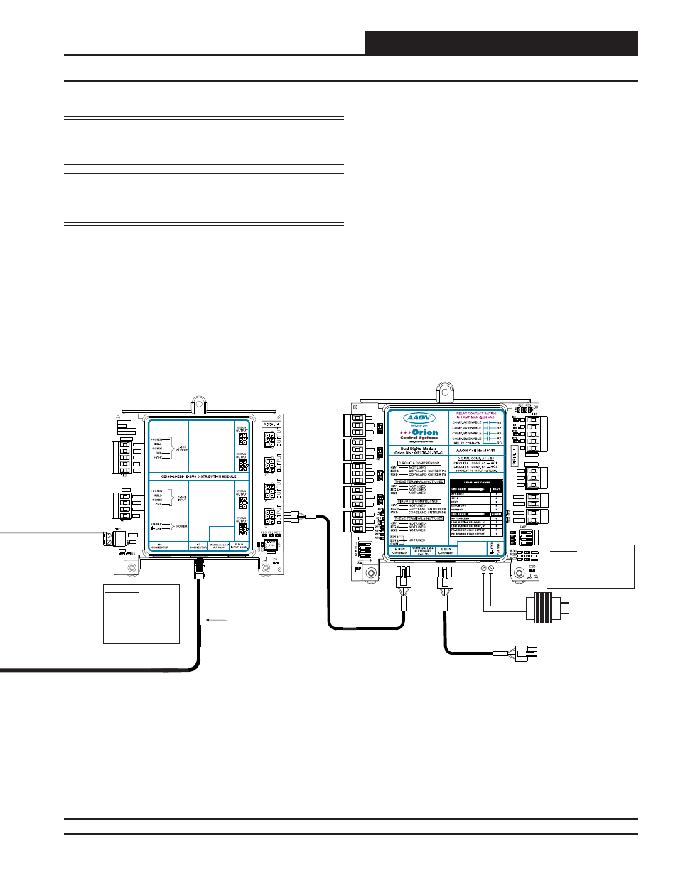
Installation and Wiring
NOTE: Contact Factory for the correct HSSC cable length for
your application. Cables are available in ¼, ½, 1, 2, 3,
4, and 5 Meter lengths and 100 and 150 Foot lengths.
WARNING: Be sure all controllers and modules are
powered down before connecting or
disconnecting HSSC cables.
Figure 4: VCM-X Modular Controller Connection to Dual Digital Module