Expansion board installation & wiring, Vav/cav controller technical guide 7, Jumper settings – Orion System MUA II Controller User Manual
Page 7: Figure 5: mua ii controller wiring, Figure 6: expansion board jumper settings, Philips, Mua ii controller, 4 relay output expansion board
VAV/CAV Controller
Technical Guide
7
7.
Before applying power to the MUA II controller, be sure
to recheck all wiring connections and terminations
thoroughly.
6.
When communication wiring is to be used to interconnect
controllers together or to connect to other
communication devices, all wiring must be minimum 18
gauge, 2 conductor, twisted pair with shield.
Line Voltage
Required VA For
Transformer = 8VA
24VAC
GND
Local Loop RS-485
9600 Baud
G - Fan ON/OFF Only
R - 24VAC
Relay Output Dry Contacts
R2 Thru R5 May Be User Configured For
The Following:
1 - Heating (Aux. Heating)Stages
2 - Cooling (Compressor) Stages
3 - Gas Reheat Control For Dehumidification
4 - External Heat Enable
Note: Up To 16 More Relays Are Available
By Adding Relay Expansion Boards. All
Expansion Board Relay Outputs Are User
Configurable As Listed Above.
Note: All Temperature Sensors Must Be Thermistor Type III Which
Provide 10K Ohms Resistance @77 Deg. F
MUA II Controller
Connect To
Expansion Board
Base (When Used)
Analog Inputs
See Individual Sensor
Wiring Diagrams For
Detailed Sensor Wiring
Connect To Next Controller And/Or
MiniLink PD On Local Loop
For Stand Alone Applications
Connect To System Manager
Warning:
24 VAC Must Be Connected So That All Ground
Wires Remain Common. Failure To Do So Will
Result In Damage To The Controllers.
All Comm Loop Wiring Is
Straight Thru
T to T
R to R
SHLD to SHLD
RL
Y1
D1
D2
D3
D4
D5
CX3
RAM
EPROM
C3
C2
U6
PHILIPS
CX6
C1
CX2
U2
U3
PAL
CX4
U4
TUC-5R PLUS
YS101816 REV. 2
V1
V2
V3
V5
V4
TB2
4
NETWORK
TOKEN
16
32
8
SW1
ADD
2
1
ADDRESS
V6
POWER
GND
24VAC
L1
D16
R6
C9
SC1
R1
1
U1
1
MC34064A
D13
C16
9936
VR2
7824CT
M
TB4
R27
C13
R10
VR1
C19
C18
NE5090NPB3192
0PS
U8
CX8
U9
X1
R7
D10
R13
D12
C7
CX10
U10
CX12
U12
U14
CX14
PJ3
PJ2
PJ1
EXPANSION
PRESSURE
SENSOR
T'STAT
C17
D15
R26
C20
R25
R24
R22
U15
CX13
U13
C15
R19
R15
C14
D18
D17
PU1
PU2
PU3
PU4
PU5
PU7
D6
D7
D8
D9
D11
D14
C12
C10
0-5
VDC
0-1
VDC
JP1
C1
1
X2
GND
TB3
INPUTS
GND
GND
+VDC
AIN1
AIN2
AIN3
AIN4
AIN5
AOUT1
AOUT2
AIN7
RN4
1
RN5
RS-485
CX5
U5
R
TB1
SHLD
T
COMM
COMM
RN3
1
RN1
U1
CX1
1
LD6
COMM
PWR
LD7
LED1
LED2
LD9
LD8
R1
U7
RV1
VREF ADJ
R28
+VREF
5.11V
TEST POINT
EWDOG
D19
RN2
1
COM1-3
COM4-5
R5
R4
R3
R2
R1
RL
Y2
RL
Y3
RL
Y4
RL
Y5
CX15
(1 MEG)
HH
P1
C21
+
_
0-10 VDC
0r 2-10 VDC
Connect To
External Heat
Device If Used
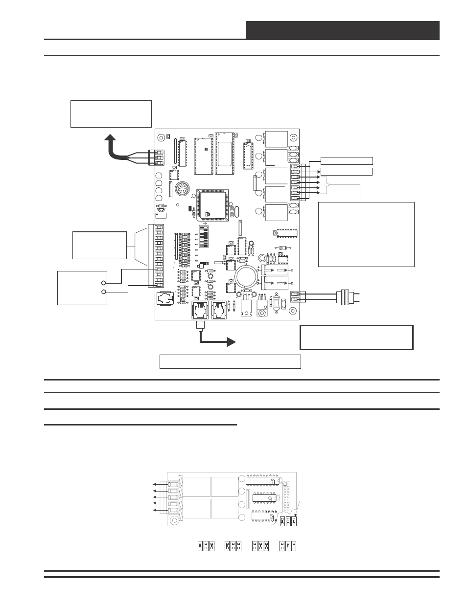
Figure 5: MUA II Controller Wiring
Jumper Settings
The expansion boards are connected to the MUA II Controller with a
modular cable. Up to 2 Expansion Base Boards can be populated with
expansion boards to provide additional inputs and outputs. The expan-
sion boards can be placed on the expansion base board in any order,
however, the jumpers on the Expansion Base Board must be set cor-
rectly for proper operation. See Figure 6 for correct jumper settings
and jumper locations.
Jumpers
Under
Expansion
Board To Be
Set As Shown
Common
N.O. Contact #6 - Configurable
N.O. Contact #7 - Configurable
N.O. Contact #8 - Configurable
N.O. Contact #9 - Configurable
4 Relay Output Expansion Board
UL5A250V
AC
G5L-114P
-PS
OMRON
CONTACT
:
24VDC
UL5A250V
AC
G5L-114P
-PS
OMRON
CONTACT
:
24VDC
UL5A250V
AC
G5L-114P
-PS
OMRON
CONTACT
:
24VDC
UL5A250V
AC
G5L-114P
-PS
OMRON
CONTACT
:
24VDC
K3
K2
4RLY IO BD.
V4
K4
YS101790
TB1
V1
K1
K3
U2
K4
RN1
PCF8574P
U1
T L
HA
AN
I D
ULN2803A/
K2
K1
74HC04N
PHILIPS
P1
CX2
CX1
Relays 6-9
Relays 10-13
Relays 14-17 Relays 18-21
Address Jumpers
Relay Outputs - 6 Through 21
Expansion Board Installation & Wiring
Figure 6: Expansion Board Jumper Settings