Sequence of operations, Technical guide mua ii controller 16, Initialization – Orion System MUA II Controller User Manual
Page 16: Mua ii configuration & setup
Technical Guide
MUA II Controller
16
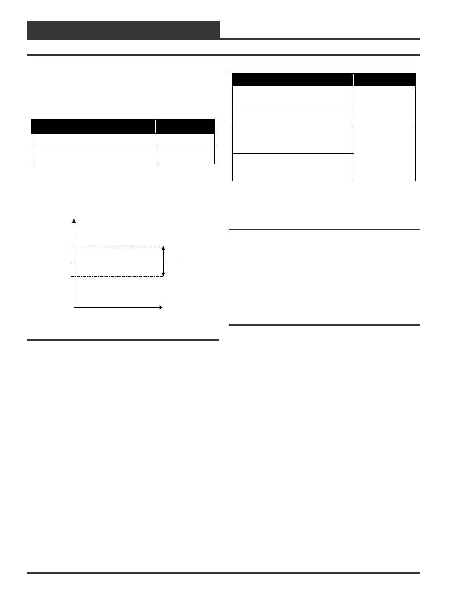
Heat
This mode occurs when the controller reads an OAT one Heating
DeadBand below the Supply Air Setpoint and a Dewpoint Tempera-
ture below the Dewpoint Setpoint. The migration table for this mode
is shown below.
Condition
Mode
OAT rises above the Heat Setpoint
Vent Mode
Dewpoint Temperature rises above
the Dewpoint Setpoint
Dehumidification
Heat Deadband
Heat Deadband
Supply Setpoint
(SAT) Supply Air
Temperature
Time
Figure 19: Heat Mode Staging
In this mode the unit will stage the Heating to deliver the Supply Air at
the Supply Temperature Setpoint. If the MODGAS II is connected
to the system, the MUA II board will send the Supply Temperature
Setpoint to the MODGAS II in order to modulate to the desired Sup-
ply Temperature. The MODGAS II will work as the first stage of
Heating. This allows having the MODGAS II working together with
standard ON/OFF heat stages. If External Heat is configured, it will
cancel the internal heat call.
External Heating
This feature is designed to control an external Hot Water Valve or an
SCR controller. Configuring a relay for External Heating Control enables
this feature. This relay is activated any time the unit needs heat. The
output follows a proportional control scheme and can be configured for
a range of 0-10 VDC or 2-10 VDC. The External Heat relay is deacti-
vated when the call for heat or reheat is canceled or the Supply Air
Temperature rises one Heating Deadband above the Supply Air Tem-
perature Setpoint.
Temperature Protect
This mode occurs when the SAT rises above the High Cutoff Tem-
perature Setpoint or drops below the Low Cutoff Temperature
Setpoint for a defined period of time. To return to the normal mode, the
SAT must drop 10° F below the High Cutoff Temperature Setpoint
or rise 10° F above the Low Cutoff Temperature Setpoint, depending
on the situation. See the table that follows.
Condition
Mode
SAT rises above the High Cutoff
Temperature
SAT drops below the Low Cutoff
Temperature
Heating & Cooling
Disabled
Blower Operation
For 3 Minutes
Then Off
After Temperature Protect is initiated
and SAT rises 10
°
F above the Low
Cutoff Temperature
After Temperature Protect is initiated
and SAT drops10
°
F below the High
Cutoff Temperature
Return to Normal
Operation
Initialization
On system powerup a 30 second start-up delay is performed where all
default setpoints are initialized, LED’s are initialized and all outputs are
turned off.
When power is first applied, LED2 is turned off for 5 seconds. At this
time the LED will “blink” to indicate the setting of the address switch
and then extinguish for another 5 seconds. The LED will now “blink”
for a 30 second start-up delay to protect the fan and other components
from short cycling during intermittent power conditions.
MUA II Configuration & Setup
There are a few configuration selections available to the user, which can
be used to tailor the software operation to match the mechanical equip-
ment this controller is installed on.
Resets
Supply Temperature Reset from Space Temperature
This feature requires a Space Temperature Sensor connected to the con-
troller. The reset is always upwards from the Supply Temp Setpoint
to the Maximum Supply temp (Maximum Supply temp = Supply
Temp Setpoint + Reset band). When the Space Temperature is at the
Min Temp Reset the desired Supply temp is the Supply Temp
Setpoint. When the Space Temperature is at the Max Temp Reset the
desired Supply temp is the Maximum Supply temp.
Outside Dewpoint Reset from Space Humidity
This feature requires a Space Humidity Sensor connected to the control-
ler on analog input AIN7. When this option is used the Fan Proof Of
Flow Switch option is not available as it also connects to analog input
AIN7. The reset is always downwards from the Outside Dewpoint
Setpoint to the Minimum Outside Dewpoint (Minimum Outside
Dewpoint = Outside Dewpoint Setpoint - Reset Band). When the Space
Humidity is at the Space Hum Min Reset the desired Outside Dewpoint
is the Minimum Outside Dewpoint. When the Space Humidity is at
the Space Hum Max Reset the desired Outside Dewpoint is the Out-
side Dewpoint Setpoint.
Sequence Of Operations