Sequence of operations – Orion System MUA II Controller User Manual
Page 17
VAV/CAV Controller
Technical Guide
17
Sequence Of Operations
Other Control Options
Fan Proof Of Flow Switch
The MUA II controller can monitor a Fan Proof of Flow Switch contact
closure on analog input #7. When this option is used the Outside
Dewpoint Reset from Space Humidity option is not available as it
also connects to analog input #7. Anytime the fan is running this contact
must be closed. If the contact does not close or remain closed no heating
or cooling outputs can activate or remain active. If this option is se-
lected, the loss of this signal can generate an alarm so that the user knows
there is a problem that needs to be corrected. There is a built-in five
second filter provided to prevent intermittent contact “bounce” from
affecting the operation. This option is not available
Remote Occupied Contact
If you have a separate source that will provide a dry contact closure to
indicate the occupied mode, you can monitor this contact closure in
place of a humidity sensor on analog input #3.
Outside Air Temperature Broadcast
If you have several Air Handlers on a job-site and they are connected
together via the RS-485 communications loop, you can select this op-
tion and configure the controller to broadcast Outside Air Temperature
to all controllers on the network, instead of installing a Outside Air
Temperature sensor on every unit. This saves the user from having to
install duplicate sensors on every air handler.
Outside Air Humidity Broadcast
If you have several Air Handlers on a job-site and they are connected
together via the RS-485 communications loop, you can select this op-
tion and configure the controller to broadcast Outside Air Humidity to
all controllers on the network, instead of installing a Outside Air Humid-
ity sensor on every unit. This saves the user from having to install
duplicate sensors on every air handler.
Relay Configuration
Output Relay Configuration
Relays #2 thru 21 can be configured for the type of function that matches
the MUA II controller options. The relays can be configured for any of
the following: Heating (aux. Heating) Stages, Cooling (compressor) Stages,
Gas Reheat Control for De-Humidification and External Heat Enable for
control of external heating devices.
Scheduling
The MUA II controller has an internal battery backed up Real Time
Clock (RTC) that allows the controller to keep the time and allows for
scheduling.
The MUA II controller has an internal 7 day schedule with 2 start-stop
events per day. You can also have 1 holiday schedule with 2 start-stop
events. This holiday schedule can be used for 14 different holiday
periods.
One thing to be noted is that you cannot view the current time when you
are viewing the MUA II controller with the Modular Service Tool or the
System Manager. You can however change the time on the MUA II
controller through the Modular Service Tool or the System Manager. If
there is any doubt on the current time, re-enter the time and date and it
will change the controller to match what you have entered. If you want
the feature of viewing the current time the MUA II Controller is using,
you must install a Personal Computer and the PRISM computer front
end software.
Alarm Detection and Reporting
The MUA II controller continuously performs self diagnostics during
normal operations to determine if any operating failures have occurred.
These failures can be reported to the user in several ways, depending on
the type of system and options installed by the user.
If a Modular Service Tool or System Manager is connected, the alarms
will be reported on the Status Screens. If the Prism computer graphic
front end is installed, the alarms will be reported on the main screen of
the program and logged to disk. If neither remote communication op-
tion is installed, the user can check for alarms by viewing LED2 on the
MUA II controller board. If everything is operating normally, the LED
will blink once every 10 seconds. If there is a problem detected, the LED
will flash a specific number of times every 10 seconds to indicate what
the problem is. These flashes or “blink codes” are described below in
order of priority. The highest priority condition must be corrected be-
fore any lower conditions can be observed and corrected. One blink is
the lowest priority and indicates no alarms. Five blinks is the highest
priority.
If the RemoteLink (modem) is installed, any alarm condition can ini-
tiate a callout to a pager to alert someone to the alarm condition. See the
Prism computer front end program operations manual for further infor-
mation on this topic.
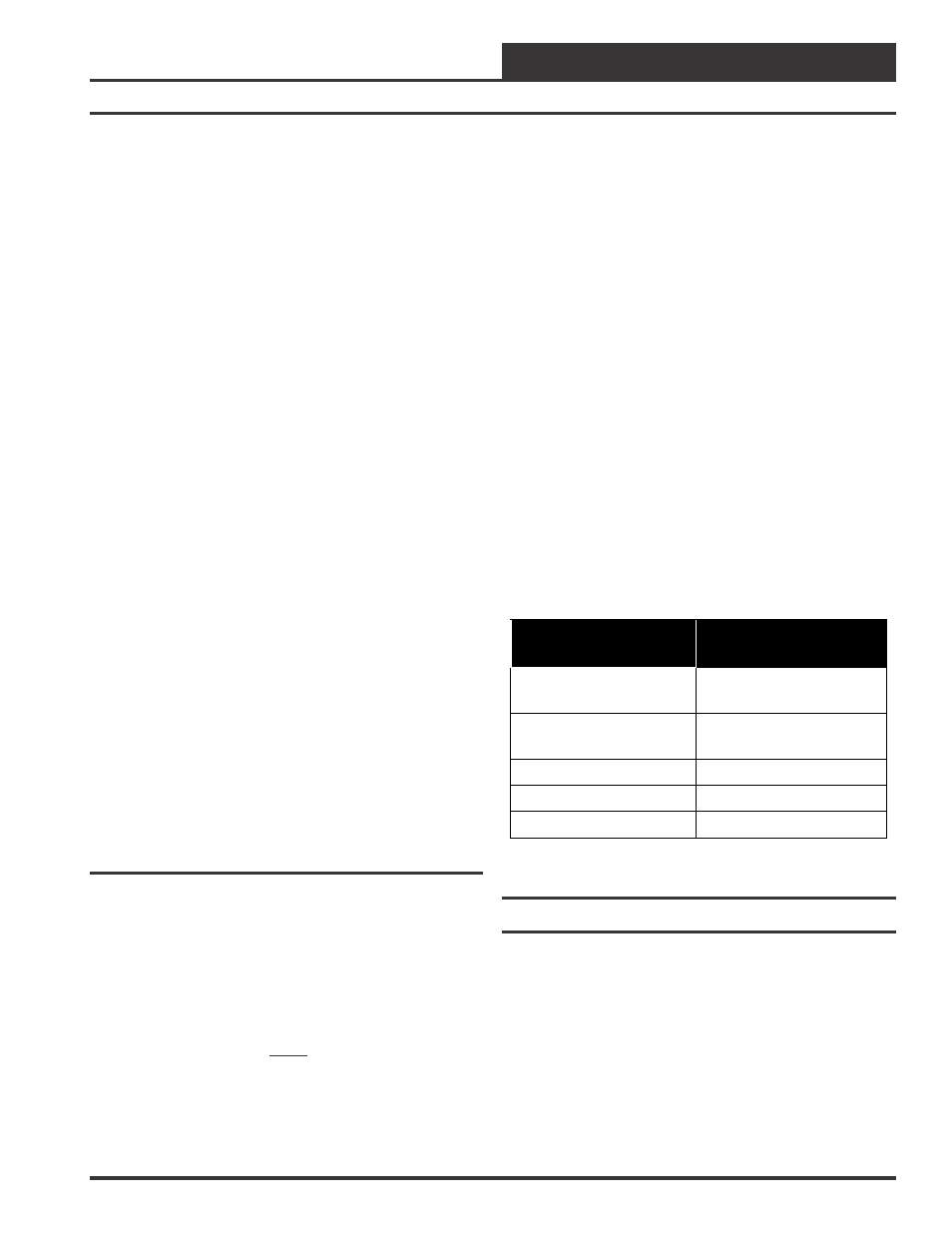
LED Blinks This
Number Of Times
Blink Code
Description
1
Normal Operations. No
Alarm Conditions
2
Sensor Failure
(OAT, OAH and SAT)
3
Mechanical Failure
4
Fan Proving Alarm
5
Unit In Force Mode
Table 2: Diagnostic Blink Codes
Force Modes or Overrides
The MUA II Controller relay outputs can be user overridden if the
Modular Service Tool or the PRISM graphical front-end program is
available. The modes of operation for the relays are:
0 = Auto (Normal Operation)
1 = Forced ON
2 = Forced OFF
The analog outputs are forced if the user specifies a value between 0.0
and 10.0 VDC. To cancel the force mode, enter a value less than zero (-
1.0 VDC).